background image

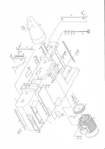
 5235 Parts’s List

Index

Description

Quantity

1

Feed Drive Motor

1

2

S Washer

4

3

Motor Lock Screw

4

4

Spped Variable Pulley

1

5

Belt Guard

1

6

S Washer

4

7

Belt Guard Lock Screw

4

8

Timing Belt

1

9

Gear Reducer (#70)

1

10

S Washer

8

11

Lock Screw

8

12

Shaft Coupling

1

13

Shaft Coupling Set Screw

4

14

Gear Reducer (#80)

1

15

Sprocket Wheel Coupling

1

16

Coupling Cover

1

17

Coupling Cover lock Screw

4

18

Bearig Plate

2

19

Flanged Bearing

2

20

S Washer

4

21

Bearing Lock Screw

4

22

Key

1

23

Connecting Shaft

1

24

Bushing

1

25

Inner Pulley Half

1

26

Bushing Lock Screw

1

27

Outer Pulley Half

1

28

Pulley Connecting Screw

3

29

Coupling AE80

8

30

Washer

8

31

Coupling Lock Screw

8

32

Universal Joint

4

33

S Washer

32

34

Universal Joint Lock Screw

32

35

Coupling AE120

2

36

Washer

2

37

Coupling Lock Screw

2

38

K125 Universal Joint 

1

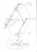
TRANSMISSION MECHANISM

Summary of Contents for 5235

Page 1: ...5235 24 Jointer Planer Owner s Manual Oliver Machinery M 5235 1 2018 Seattle WA Copyright 2003 2018 info olivermachinery net www olivermachinery net...

Page 2: ......

Page 3: ...se abuse negligence accidents unauthorized repairs alterations lack of maintenance acts of nature or items that would normally be consumed or require replacement due to normal wear In no event shall O...

Page 4: ...per Portion Of The Machine 13 Setting The Size 14 Setting The Front Fence 15 Adjusting The Feed Chain 16 Machine Features 17 18 Adjusting The Feed Rollers 19 20 Adjusting The Tension 19 Adjusting The...

Page 5: ...dvice from a supervisor or other qualified person 3 The machine should be disconnected from the power source before performing maintenance or adjustments ot the internal mechanisms or when making repa...

Page 6: ...ave the machine running unattended 14 The employer is responsible for selecting competent and qualified employees 15 The employer must make sure that employees study and utilize this safety informatio...

Page 7: ...g sleeves neckties etc should not be worn 24 Do not wear gloves or other hand covering articles around moving machinery 25 Cover long hair with a hair net or cap 26 Protective guards and shields must...

Page 8: ...5235 Max Working Width 18 457mm 24 610mm Max Working Thickness 4 51 64 120mm 8 200mm Max Working Length 12 300mm 12 300mm Composition Of Knives Solid Carbide Solid Carbide Knife Style 30mm x 12mm x 1...

Page 9: ...ensions are 5230 L2650 x W1550 x H1800 mm 5235 L2950 x W1850 x H1830 mm While in the packing crate the machine should be lifted and moved by a forklift Attention should be paid to the balance of the m...

Page 10: ...ng 3 Secure all movable parts of the machine and remove movable accessories before moving 4 The transportation should be done only by trained and qualified personnel 5 Keep all other people away from...

Page 11: ...ow the safe feeding and removal of workpieces from the machine The ground should be flat and rigid enough to support the machine it is not necessary to bolt the machine to the ground Place steel plate...

Page 12: ...necting or disconnecting power or performing any maintenance or inspection work always switch this device to the OFF position and lock it to prevent accidental starting After the power has been connec...

Page 13: ...d feed conveyor running The machine is then ready to start planning The feed conveyor can only be started when the lower and upper spindles are running If the upper or lower spindles stop running the...

Page 14: ...achine are located at the lower front side of the machine A hand wheel is located below the elevation buttons for fine adjustment of the working thickness of the workpiece A hand wheel located under t...

Page 15: ...e the elevation buttons and micrometric adjustment hand wheel to move the upper portion of the machine so that the upper planning amount is set The total amount to be planed will be read on the thickn...

Page 16: ...ecome clogged and damaged There is a fence at the infeed side to prevent workpieces from being fed in such a way that too much material would be removed at one time The upper portion of the machine sh...

Page 17: ...ng and excess noise during workpiece feed Tighten the screws to increase tightness To adjust the pressure loosen the fixing lever on the eccentric board and move the eccentric board up or down to obta...

Page 18: ...l cabinet 7 Infeed table 8 Infeed table elevation hand wheel 9 Spike conveyor feed chain 10 Lower cutterhead thickness gauge 11 Thickness gauge 12 Micrometric elevation adjustment hand wheel 13 Elevat...

Page 19: ...18 15 9 16 14 13 12 10 11 8 7 6 5 4 1 2 3 17 18...

Page 20: ...steel rollers on the bottom the top rollers are pressure rollers and keep the workpiece from jumping during feed To adjust the tension of the rollers adjust the pressure screws and nuts located at ei...

Page 21: ...sults the lower roller should be adjusted so that the top of the roller extends 0 55mm over the table The roller should always be parallel with the table To Adjust the roller turn the screws on the si...

Page 22: ...a workpiece onto the feed bed under the front and rear pressure plates To adjust the rear pressure plate turn the screws located at the side of each pressure plate See figure below The pressing keys...

Page 23: ...r and belt On the front of the machine swing the cutterhead support tray to perpendicular position and fix it in place with the lock lever Pull the cutterhead out of the machine and fix the cutterhead...

Page 24: ...cutterhead is not parallel to the table and needs to be adjusted Open the front door and access the lower cutterhead Prevent the cutterhead from rotating by fixing the lock pin Loosen the fix screw as...

Page 25: ...upper cutterhead open the rear door and access the elevation rod for the upper portion of the machine See figure Loosen the three scres that are located at the connection point of the rod and vertical...

Page 26: ...ettings shown in the table below Turning the selector knob clockwise increases feed speed turning it counterclockwise decreases feed speed WARNING Do not change the feed speed when the machine is not...

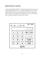
Page 27: ...unt on the keypad and press the SET key for 2 3 seconds Press the START key to have the machine automatically move to the desired thickness The UNIT key will switch the setting to inches mm or Chinese...

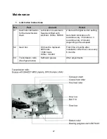
Page 28: ...nt Oil No RW 68 2 liters with digital control setting Automatic lubrication of 3 seconds every 3 minutes or 3 seconds every 2 minutes depending on feed speed 02 Gear box Oil must be replaced 400 hours...

Page 29: ...6 Grease EP2 Transmitting gear box Worm gear Snazzy VG 220 HLP 90 Shell OMala VG 460 3 Standard Accessories List and Applications No Part Quantity 01 Tool kit 1 set 02 Shims plate 8 pieces 03 Tool gau...

Page 30: ...e angle of the cutting knife 42 while grinding the knife c The bottom cutting knife spindle must be wiped clean and lubricated before the spindle may be drawn out 6 Recommendation for Dust Collection...

Page 31: ...ntenance work B Disconnect the power from the hand operated power disconnection device before starting maintenance work C Be sure to check that all personnel are clear of the movable guards before rec...

Page 32: ...r G Place the roller unit on the wood block in its mounted position H Lower the upper portion onto the roller unit and adjust to proper position then affix with screw I Secure the roller unit verify e...

Page 33: ...t front and rear end 6 Incorrect position of outfeed rollers 1 Adjust feed conveyor tension 2 Adjust table roller position 3 Reduce cutting load 4 Reduce feed speed 5 Do not feed such workpieces 6 Adj...

Page 34: ......

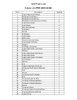
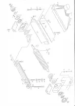
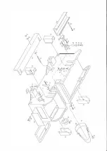
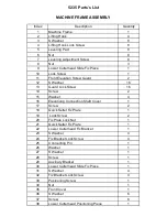
Page 35: ...Fix Plate Lock Screw 2 17 Upper Belt Guard Lock Screw 1 18 Washer 4 19 Upper Belt Guard lOck Screw 1 20 Upper Belt Guard 1 21 Upper Belt Guard Lock Screw 2 22 Disk Washer 2 23 Spring 1 24 Nut 2 25 Upp...

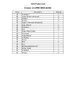
Page 36: ...feed Fence Lock Screw 2 41 Washer 4 42 Screw 4 43 Upper Cutterhead Drive Motor 1 44 Hard Washer 4 45 S Washer 4 46 Nut 4 47 Upper Motor Pulley 1 48 Fix Collar 1 49 Hard Washer 1 50 S Washer 1 51 Screw...

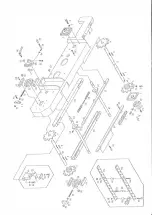
Page 37: ...J _Y w iJ w w f...

Page 38: ...crew 6 16 Guide Rail 2 17 Feed Chain 2 18 Rear Eccentric Shaft 1 19 Sproket Wheel 2 20 Chain 1 21 Chain Tension Adjustment Screw 1 22 Lower Guide Rail 2 23 Front Eccentric Shaft 1 24 Sprocket Wheel Se...

Page 39: ...de Rail Fix Screw 6 44 Eccentric Shaft Support 4 45 Washer 8 46 Eccentric Shaft Lock Screw 8 47 Eccentric Shaft Fix Plate 4 48 S Washer 8 49 Screw 8 50 Spike Plate Thick 50 51 Spike Plate Thin 50 52 S...

Page 40: ...I w I ri J I X I y w cS l c n 0 D I I I I I I I I I I I I...

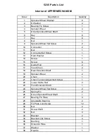
Page 41: ...cket Wheel Coupling 1 16 Coupling Cover 1 17 Coupling Cover lock Screw 4 18 Bearig Plate 2 19 Flanged Bearing 2 20 S Washer 4 21 Bearing Lock Screw 4 22 Key 1 23 Connecting Shaft 1 24 Bushing 1 25 Inn...

Page 42: ...39 Washer 8 40 Universal Joint Lock Screw 8 41 Gear Reducer Protection Screen 1 42 S Washer 5 43 Protection Screen Lock Screw 5 44 Pulley Connecting Screw 1 45 Pulley With Protect Guard 1 46 Timing B...

Page 43: ...I I I I C _ t en _ 7 0 J a f 1 r I I I I I I I I I...

Page 44: ...ouble Round End Key 10 10 40 1 12 Nut 1 13 Bearing Cap 1 14 Bearing Cap Lock Screw 3 15 S Washer 4 16 Bearing Housing Lock Screw 4 17 Knife Spring 8 18 Knife Spring 4 19 Gib 4 20 Knife Lock Screw 40 2...

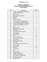
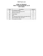
Page 45: ...escription Quantity UPPER CUTTERHEAD 37 Front Pressure Plate 18 38 Spring Tension Adjustment Nut 18 39 Spring Lock Screw 18 40 Lock Screw 2 41 Nut 2 42 Front Pressure Plate Position Adjustment Screw 2...

Page 46: ...c w 0 ru 0 tJ1 ml w I ll...

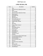
Page 47: ...Upper Roller Smotth 1 13 Key 2 14 Bushing 2 15 Upper Roller Coarse 1 16 Spring 72 17 Roller Spring Plug 72 18 Roller Clamp 24 19 Clamp Nut 2 20 Roller Bracket 2 21 Clamp Nut 1 22 Shaft Connector 2 23...

Page 48: ..._ J1 ___ I Io o I i I i i ffi I Wru I J 0 I 8 111...

Page 49: ...her 4 16 Elevationg Connection Shaft Cover 1 17 Screw 2 18 Quick Setter Fix Plate 1 19 Lock Screw 2 20 Fix Plate Lock Nut 1 21 Quick Setter Fix Plate 1 22 Lower Cutterhead Fix Bracket 1 23 S Washer 4...

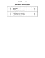
Page 50: ...List Index Description Quantity MACHINE FRAME ASSEMBLY 39 WSWasher 2 40 Screw 2 41 Lower Dust Hood Connector 1 42 Screw 3 43 Rear Elevation Screw Guard 2 44 Lower Cuttehread Belt Guard 1 45 Belt Guard...

Page 51: ......

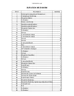
Page 52: ...crew 24 14 Screw 16 15 Connector Shaft 2 16 Key 6 17 Connector 3 holes 6 18 90 Direction Changer 2 19 S Washer 8 20 Screw 8 21 Elevation Gear Box 2 22 S Washer 12 23 Screw 12 24 Connector Shaft 1 25 E...

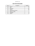
Page 53: ...5235 Parts s List Index Description Quantity ELEVATION MECHANISM 39 Screw 16 40 Nut 4 41 S Washer 16 42 Screw 16 43 Digital Rearout Sensor 1 44 Sensor Fix Plate 1 45 S Washer 2 46 Screw 2...

Page 54: ...I I I I rnimo I i f J...

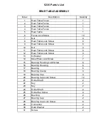
Page 55: ...Nut 0 11 Rear Table Lock Screw 0 12 Rear Table Lock Screw 0 13 S Washer 7 14 Steel Plate Lock Screw 7 15 Bearing Housing Lock Screw 6 16 Bearing Housing 6 17 Bearing 6 18 Bearing Clamp 4 19 Bearing Ca...

Page 56: ...30 L tl I l i I h I vi I I 34 1 35 36...

Page 57: ...wer Cutterhead 1 11 Thickness Indicator 1 12 S Washer 2 13 Thickness Indicator Screw 2 14 Screw Support 1 15 S Washer 2 16 Screw Support Lock Nut 2 17 Screw 2 18 Nut 2 19 Nut 1 20 Screw 1 21 Key 1 22...

Page 58: ...rt B r I I I v I I A 0 r r I V r_jJ _ I I I I I I I I __ L__j___ I I 7 r I j I I I a...

Page 59: ...Screw 3 10 Bushing 1 11 Pulley 1 12 Nut 2 13 Belt 3 14 Bearing 6309V 1 15 Nut 1 16 Bearing Cap 1 17 Bearing Cap Lock Screw 3 18 Spring 1 19 Knob 1 20 Knife Spring 8 21 knife Spring 4 22 Gib 4 23 Knif...

Page 60: ..._ 1U W J 1 CP...

Page 61: ...0 Gib 1 11 Nut 4 12 Screw 4 13 Nut 1 14 Screw 1 15 Key 1 16 Thrust Bearing 4 17 Lower Slide Set Screw 4 18 Lower Slide 1 19 Slide Pad 2 20 Hard Washer 2 21 Screw 2 22 Gear 1 23 Gear 1 24 Screw 2 25 Bu...

Page 62: ......
Reviews: