

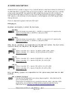


RS232
The board can be programmed via the RS232 connector (serial interface). This is done without the need
of an additional programming tool. However, you would need a proper serial cable or adapter to access it.
You would also need to change the positions of three PTH jumpers (the rest of the jumpers should be as
per default):
1. B0_0/B0_1 should be set to position B0_1 – which means boot from system memory
2. RST_E should be closed
3. BOOT_E should be closed
Do not confuse B0_0/B0_1 with B1_0/B1_1.
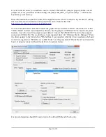
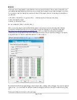
After you set the jumpers and establish the hardware connection you need to download the software
provided by STMicroelectronics. It is called “Flash Loader Demonstrator”. It might be found here:
http://www.st.com/web/en/catalog/tools/PF257525
– after you install the software and establish
connection you can upload hex files to the board without the need of an expensive debugger. A properly
recognized board in “Flash Loader Demonstrater” is shown below:
Note that this method of programming is much slower than working with a debugger. Not only the upload
speed is low – you would need to perform hardware debugging routines to be able to track what is going
on.
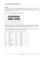
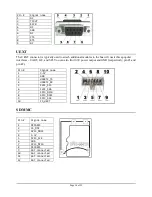
The layout of the port is shown on the next page:
Page 15 of 23