background image

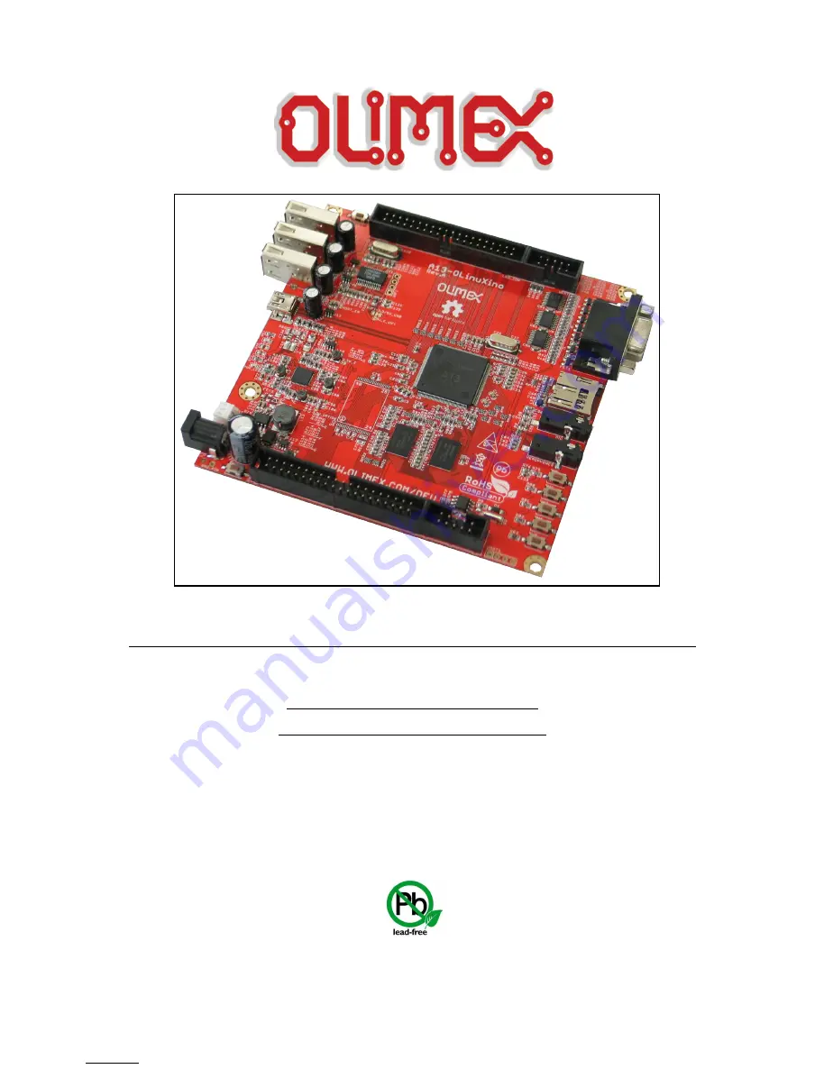
A13-OLinuXino and A13-OLinuXino-WIFI

Open-source single-board

Android 4.0 mini-computer

USER’S MANUAL

Revision F,  March 2013

Designed by OLIMEX Ltd, 2012

All boards produced by Olimex LTD are ROHS compliant

Elcodis.com


electronic components distributor


All manuals and user guides at all-guides.com

Summary of Contents for A13-OLinuXino

Page 1: ...single board Android 4 0 mini computer USER S MANUAL Revision F March 2013 Designed by OLIMEX Ltd 2012 All boards produced by Olimex LTD are ROHS compliant Elcodis com electronic components distribut...

Page 2: ...sed including but not limited to implied warranties of merchantability or fitness for purpose are excluded This document is intended only to assist the reader in the use of the product OLIMEX Ltd shal...

Page 3: ...ting the A13 OLinuXino 12 2 6 5 Downloading the default config file and script tool 13 2 6 6 Applying the script and uploading the confing 13 2 6 7 Restarting the A13 OLinuXino 13 2 7 Configuration of...

Page 4: ...Jumper description 28 6 8 1 CE_NAND_E 28 6 8 2 3 3V_OPTION 1 5V_E 28 6 8 3 5V_E 28 6 8 4 HOST_EN 5V_E_WIFI WIFI 3 3V 5V_USB 28 6 9 Additional hardware components 28 CHAPTER 7 SCHEMATICS 30 7 Introduc...

Page 5: ...gn 3 1 USB Host 3 available for users 1 for optional WIFI RTL8188CU 802 11n 150Mbit module on board 1 USB OTG which can power the board SD card connector for booting the Linux image optional 4GB NAND...

Page 6: ...perating system image on board while the second has two additional components a WIFI module on the board and NAND memory with stored Android image The information on A13 OLinuXino Micro will be added...

Page 7: ...order to set up the OLinuXino optimally the following items are required 6V to 16V 6W required 6V 1A or 16V 0 4A for optimal power LCD preferably with touchscreen panel display for the LCD_CON OR TV...

Page 8: ...flickering and not sufficient power If you suspect the power is not enough for the peripherals you have connected use the PWR jack The board can be also powered by the USB OTG connector mini USB stan...

Page 9: ...do as follows run Livesuit disconnect the power supply and USB cable then press HOME button apply power supply attach USB cable and release the button Livesuit will detect the bootloader and will ask...

Page 10: ...It is worth mentioning that we used Ubuntu with Linux Kernel 3 2 for the steps below 2 6 1 Getting the Android SDK tools Download the Android SDK tools for Linux from http developer android com sdk i...

Page 11: ...we extracted the tools folder tools in point 1 and start it android From the check boxes select to install Android SDK Tools Android SDK Platform Tools and Android 4 0 API check the screenshot Page 1...

Page 12: ...vice However if we get bash adb No such file or directory we have to check if the ia32 libs are installed if not we install them with apt get install ia32 libs If again the device is not listed we try...

Page 13: ...n we execute from the console chmod x script 2 6 6 Applying the script and uploading the confing After we have edited the file as we win we do script A13_config_600x800 fex_ok and then we push it on t...

Page 14: ...d might differ from the names used below to describe them For the actual names check the A13 OLinuXino board itself 3 1 Layout top view The picture above shows the initial revision of A13 OLinuXino No...

Page 15: ...Cache Mali 400 3 D Engine VPU HD Video Decoding 1920 1080 30fps Support H 264 H 263 VC1 Mpeg1 2 4 Divx 3 4 5 6 Xvid VP6 8 AVS etc HD Video Encoding Support encoding in H 264 format Up to 1920 1080 at...

Page 16: ...rful Acceleration Graphic 3D Mali400 MP VPU 1080P APU E Reader Ultra low System Power Consumption 15 20 lower than competitors Smart Backlight auto adjust backlight acc to the image display Package eL...

Page 17: ...12 A13 OLinuXino user s manual 4 2 Block diagram The block diagram is taken from Allwinner s datasheet Page 17 of 37 Elcodis com electronic components distributor All manuals and user guides at all gu...

Page 18: ...nected to pins 1 and 2 of the RTC_MODULE PCF8563T 5 3 Power supply circuit The power supply is handled mainly by AXP209 power management system an Allwinner chip that goes together with the A13 proces...

Page 19: ...u will also need a software tool LiveSuit and a newer firmware image if you wish to upgrade the firmware The LiveSuit tool may be downloaded from the A13 wiki page The simple steps for upgrading the f...

Page 20: ...1 3 3V 2 SDC0_SCK 110 3 SDC0_DATA3 112 4 GND Consider the above table when connecting the USB SERIAL CABLE F according to the wire color code If having A13 OLinuXino with 1xUART0 and the table with th...

Page 21: ...of the lower quality microSD cards might draw too much current from the slot which might cause power state problems If you suspect the microSD card is causing problems please try using another one of...

Page 22: ...onnector Pin Signal Name Processor Pin 1 3 3V 2 GND 3 UART1_TX 152 4 UART1_RX 151 5 TWI2_SCK 161 6 TWI2_SDA 160 7 SPI2_MISO 117 8 SPI2_MOSI 116 9 SPI2_CLK 115 10 SPI2_CS0 114 The UEXT pinout is also p...

Page 23: ...PIN1 10 PIN2 PIN0 PIN1 PIN2 and PIN3 are connected to the power regulator module AXP209 6 5 GPIO 2 General Purpose Input Output 40pin connector The GPIO pins are led out on a separate 40pin connecter...

Page 24: ...8 PIN33 122 19 PIN11 TWI1 SDA 106 20 PIN32 121 GPIO Pin Signal Name Processor pin GPIO Pin Signal Name Processor pin 21 PIN12 NWE 8 22 PIN31 120 23 PIN13 NALE 7 24 PIN30 119 25 PIN14 NCLE 6 26 PIN29 1...

Page 25: ...convenience LCD_CON connector GPIO Pin Signal Name Processor pin GPIO Pin Signal Name Processor pin 1 5 2 GND 3 3 3 4 GND 5 LCD_D18 135 6 LCD_D18 135 7 LCD_D18 135 8 LCD_D19 134 9 LCD_D20 133 10 LCD_...

Page 26: ...ts 1 5A maximum to the board Pin Signal Name 1 Power Input 2 GND More info about the power supply can be found in chapter 5 of this manual 6 8 Headphones and microphone connector Standard audio jack a...

Page 27: ...bottom of the board under the connector 6 7 VGA video connector The female DB15 connector is used for video output on a monitor At the moment the maximum achieved resolution is 800x600 due to limited...

Page 28: ...ions The default positions are closed 6 8 3 5V_E The jumper provide a test pad during production and debugging checking the supply voltages It is not recommended to change its default position It is a...

Page 29: ...first revisions of the board is hynix H5TQ2G83CFR H9C 1 x 32Gb 4096M x 8 bit NAND FLASH the exact memory is hynix H27UBG8BTR only present in A13 OLinuXino WIFI LED1 CHLED PWR_LED GPIO LED battery cha...

Page 30: ...You are allowed to view and edit the schematics as long you keep them free and you mention the source address e g www olimex com The EAGLE schematic is situated on the next page for quicker reference...

Page 31: ...X2 1 2 C E_ N AND _E 1 2 1 5V_E 1 2 3 3V_E 1 2 3 3V_OPTION 1 2 5V_E 1 2 5V_E_WIFI C1 C2 C3 C4 C5 C6 C7 C8 C9 C10 C11 C12 C13 C14 C15 C16 C17 C18 C19 C20 C21 C22 C23 C24 C25 C26 C27 C28 C29 C30 C31 C32...

Page 32: ...ons are in mils The three highest elements on the board in order from the tallest to the shortest are capacitor C126 650mils the three USB hosts 500mils the VGA connector 475mils Page 32 of 37 Elcodis...

Page 33: ...revision Revision Changes Modified Page A 19 09 12 Initial Creation All B 21 09 12 Page 9 Fixed several errors in voltage requirements and power consumption 9 C 24 09 12 Pages 8 9 Fixed a typo of the...

Page 34: ...clear that the standard version lacks NAND and WIFI 9 10 29 37 F 21 03 13 Pages 9 19 added info about LiveSuit and cleared the instructions Page 29 fixed erroneous memory descriptions Pages 20 22 adde...

Page 35: ...ll regulators 6 moved couple of elements for better distance between each other D 1 Removed resistor matrices except the ones near DDR3 memories to lower fault rates 2 Added header NA HN1X2 so you can...

Page 36: ...Xino with added NAND memory Android image and MOD WIFI_RTL8188 A13 OLinuXino the lite version of A13 OLinuXino with no external NAND and no embedded internet interface USB SERIAL CABLE F USB serial co...

Page 37: ...re powered Please note that warrany do not cover problems caused by unproper use shorts over voltages ESD shock etc If the board has warranty label it should be not broken Broken labels void the warra...

Reviews: