3 Installation
8
3.5 operation system
Hook the component assembly onto the base plate as shown.
Attach it with 8 allen head screws
3.6 Cover
Opening the cover
Page 1: ...TS Please note Programming of the open and close stop points will occur after installation An uninstalled unit will result in constant motor rotation For any questions feel free to contact us INSTALLATION MANUAL Olide DSW 120N ...
Page 2: ...th a keypad 10 4 2 Connections with a microwave sensor 11 4 3 Connections with PIR sensors 11 4 4 Connections for a safety motion top scan 11 4 5 Connections for push buttons 12 4 8 Connections for magnetic locks 13 4 9 Connections for electric locks 13 4 10 Connection with the touchless hand sensor switches 13 4 11 Double door synchronous settings 14 4 12 Wireless push buttons settings 15 4 13 Re...
Page 3: ... degrees Hold Open Time 1 30 sec Adjustable Max Door Frame Depth Door Width Max 1200mm 47 2 Max Opening Angle 450mm 17 7 Min 660mm 26 120 degrees Environment Temperature 20C to 50C 4F to 122F Protection Class IP12D Product Weight 6 5Kg 14 3lbs Dimensions L515 x H95 x W50mm 20 3 L x 2 W x 3 75 H ...
Page 4: ...nent Power cable hole Pull Arm Option for interior opening Push Arm Option for exterior opening 2 Base Plate Sensor cable hole Motor Assembly Off On Switch Motor Gear box Control block Motor output Cover Plate ...
Page 5: ...stallation 3 1 Installation example Pull Arm The door opens to the inside toward the unit using the pull arm assembly Push Arm The door opens to the outside away from the unit using the push arm assembly 3 ...
Page 6: ...ed to the frame with eight wood screws or eight M6 15 countersunk screws Please note that 20mm sensor cable hole is always to the right side and that the power cable access is always to the left The sensor cable access hole is very near the edge of the plate 0 59 15mm 1 5 38 5mm 18 2 464 5mm 0 59 15mm 1 5 38 5mm As the picture shows the base plate should be mounted to the frame with eight wood scr...
Page 7: ...when left hand installation At door right 240 9 44 240 9 44 20 160 6 3 Fix the slide rail of pull arm on the door panel as shown using three round head wood Screws if the door panel is steel please use M6 15 cross recessed head screws Attach the slide rail of the pull arm on the door panel as shown using 3 screws 0 78 29 1 44 ...
Page 8: ...ngth according to the door depth L until the angle between the push arm and the door panel is 90 At door right 6 50 1 96 290 11 42 Fix the support holder of push arm on the door panel as shown using two round head wood screws if the door panel is steel please use M6 15 cross recessed head screws 35 1 29 ...
Page 9: ...3 Installation 7 3 4 Installation of Push arm Stop screw Adjust the stop screw position slotted hole to allow full opening of the door Do not exceed 90 ...
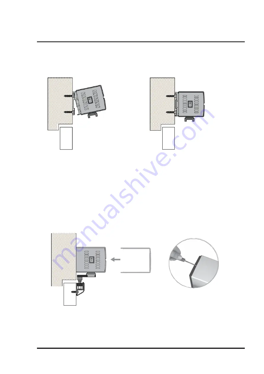
Page 10: ...3 Installation 8 3 5 operation system Hook the component assembly onto the base plate as shown Attach it with 8 allen head screws 3 6 Cover Opening the cover ...
Page 11: ...3 Installation 9 3 7 Connect pull arm to the operation system 3 8 Connect the push arm to the operation system M M Motor output shaft ...
Page 12: ...4 Electrical Connections 4 10 Control panel details Power input located on the left side of the component assembly 4 1 Connections with a keypad ...
Page 13: ...4 Electrical Connections 4 11 4 2 connections with a microwave sensor 4 3 connections with PIR sensors 4 4 Connections for a safety motion top scan ...
Page 14: ...4 Electrical Connections 4 12 4 5 Connections for plastic push buttons 4 6 Connections for wiring disabled push buttons 4 7 Connections for wireless handicapped push buttons ...
Page 15: ...4 13 4 8 Connections for magnetic locks Need to press the lock button on remote control for the first close then it will auto lock when close 4 9 Connections for electric locks 4 10 Connections for hand sensor touchless switch ...
Page 16: ...Connector COM COM safety sesnsor close safety sensor close safety sensor open safety sensor open interlock input interlock input COM COM interlock output Please use the hand programmer for setting the double door synchronous The detailed steps and written on the Page 17and 18 interlock output 4 11 Double door synchronous connections double door synchronous ...
Page 17: ...nd release the encode button 2 Code Press encode button once buzzer is sounding now press the PRESS button the buzzer stops sounding that indicate the code is successfully learned When using the remote control the buzzer will sound for 2 seconds 3 Note When you use the PRESS buttons the buzzer beep two times indicate that the PRESS button learning is failed please do once more step 2 Code Learning...
Page 18: ...tton until the buzzer sounds Then press any button on the remote control The buzzer should silence which means that encoding is complete 3 Now when the remote control is used the buzzer will sound for 2 seconds If the buzzer beeps twice the encoding has failed Repeat step 2 4 When pressing the automatic button D one time the door will open and close one time Note No more than 10 remotes can be use...
Page 19: ...2 master slave cs closing speed n3 synchronize settings cd closing low speed angle o manual open door settings jb closing force L lock mode selection ok opening hold time F open direction settings P door closer settings increase operation increase data decrease operation decrease data function select confirm parameter data next parameter parameters saved parameters send TEST check settings and tes...
Page 20: ...5 Parameters Adjustment 18 5 2 adjustment steps ...
Page 21: ...en the door in half open then power on the door goes to closing direction if not change the open direction rebound when closing the door repeat open and close actions 1 clear the obstacle away 2 Increase the closing force with the hand programmer Lock not work Need to press the lock button on remote for the fist close 19 ...