5.
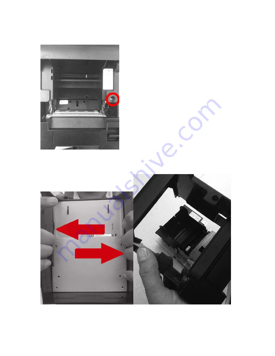
Remove the screw on the top right hand side of the machine.
6.
Pull the side of the molding away and the bottom print mechanism will slide out of the cover exposing the print engine and components.
Page 1: ...31 Disassembly Instructions 1 Remove the 4 marked screws on the base of the unit to remove the internal power supply PT331 only 2 Disconnect the power supply cable and remove the power supply casing P...
Page 2: ...3 Remove the top cover by pushing out on the plastic brackets holding the cover in place 4 Remove the platen roller assembly by removing the 2 screws on the top cover...
Page 3: ...5 Remove the screw on the top right hand side of the machine 6 Pull the side of the molding away and the bottom print mechanism will slide out of the cover exposing the print engine and components...
Page 4: ...7 Remove the 2 screws and 3 wired connections 8 Remove the screw from the left side and the 2 wired connections...
Page 5: ...9 Remove the screw from the right side 10 Detach the media roll assembly...
Page 6: ...sembly Slide the mechanism toward you and up You will still have one ribbon cable attached It is easier to remove with the assembly mostly detached 12 The main board is now exposed You can remove that...
Page 7: ...13 To remove the stepping motor remove the screw and pull motor out 14 Remove the 2 screws to detach the print head Disassembly is complete...