2 – 10
(d)
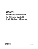
Simultaneous Compensation of the number of impact pins
The MPU is provided with the compensation table for each pin to compensate as
necessary.
Number of impact pins
Few
Many
Drive time
Short
Long
Print Head
Time
Pin 3~6
Pin 1, 2,
8, 9
Pin coil
current
Pin 1, 2
3~6
8, 9
Platen
Print Compensation Control
The print compensation methods are shown below:
(a)
Voltage compensation (See 2.1.8 “Alarm Circuit.”)
(b)
Temperature compensation (See 2.1.8 “Alarm Circuit.”)
(c)
Pin stroke compensation
As shown in the drawing left, the stroke length
up to the platen is different for each pin.
Summary of Contents for MICROLINE 320
Page 7: ...1 2 1 2 Options 1 Cut sheet feeder unit CSF Attachment assy 2 Pull tractor assy Single bin CSF...
Page 8: ...1 3 3 Bottom push tractor unit 5 Serial I F RS 232C 4 Roll paper stand Narrow only...
Page 36: ...2 28 Figure 2 6 Ribbon cartridge Drive gear Ink reservoir...
Page 51: ...2 43 Platen Figure 2 16 Ribbon protector Printhead Carriage frame assembly...
Page 90: ...5 2 Carriage shaft...
Page 98: ...5 10 9 Carriage Assy NK2 10 SUS Bearing part of the guide roller EM 30L B...
Page 119: ...6 21 Replace RS232C board Remedied No Yes End Replace driver board...
Page 121: ...B 1 B SPARE PARTS LIST...
Page 122: ...B 2 Figure 11 1 Upper Cover Assy 1 2 3 4...
Page 124: ...B 4 Figure 11 2 Printer General Assy 6 9 8 2 7 4 5 3 10 1...
Page 129: ...B 9 Figure 11 4 Carriage Assy 12 9 8 6 14 11 10 1 13 7 5 4 3...
Page 131: ...B 11 Figure 11 5 Option Spare Parts 1 2 3 4 5 6 7 Pull Tractor Bottom Tractor I F Board...
Page 145: ...Microline 320 321 Turbo Service Manual Part Number 59273701 Printed in the USA...