Oki ML421 Series Maintenance Manual Download Page 41

 42113901          Rev.2 

41 /

Oki  Data  CONFIDENTIAL

(2)

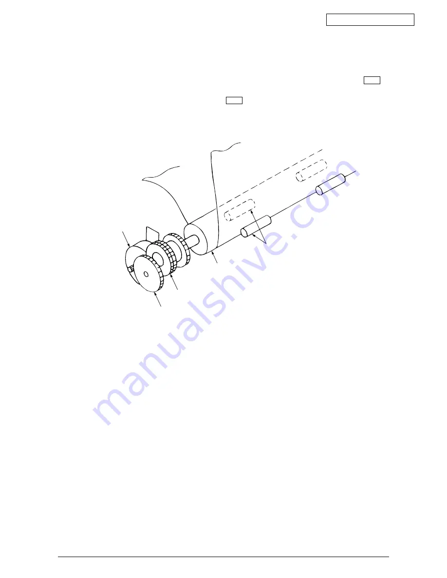
Cut-sheet feeder operation (See Figure 2-8.)

The pulse motor used for the paper feed mechanism is mounted on the left of the frame,
and the rotation of the motor is transmitted through decelerating gears (LF idle gear, platen
gear) to the platen. When using cut-sheet paper, the change lever must be in the  TOP
position to grab the paper, while disengaging the push tractor.

When the change lever is set to the  TOP  position, the cut sheet is automatically fed
in up to the print start position after pausing for the wait time stored in the menu.

Figure 2-8

LF ldel gear

Platen gear

Platen

Stepping motor

(LF motor)

Pressure roller

Summary of Contents for ML421 Series

Page 1: ...42113901 Rev 2 1 133 Oki Data CONFIDENTIAL ML420 421 PRINTER Maintenance Manual ODA...

Page 2: ...42113901 Rev 2 2 Oki Data CONFIDENTIAL...

Page 3: ...printer in the field This manual is for customer engineers For further information refer to the Users Manual for handling or operating the equipment The relation between the destination point and the...

Page 4: ...peration 38 2 2 6 Paper Detection Mechanism 48 2 2 7 Automatic Sheet Feed 50 2 2 8 Paper Park Function 52 3 ASSEMBLY DISASSEMBLY 53 3 1 Precaution for Parts Replacement 53 3 2 Service Tools 54 3 3 Dis...

Page 5: ...r Printhead and SP LF Motor 100 6 5 Troubleshooting flow chart 102 APPENDIX A PCB LAYOUT 114 APPENDIX B SPARE PARTS LIST 115 APPENDIX C RS 232C SERIAL INTERFACE BOARD OPTION 126 1 GENERAL 126 2 OPERAT...

Page 6: ...d Printer Configuration This printer consists of the following assemblies Figure 1 1 Configuration Upper cover Access cover assy Platen knob Sheet guide assy Control board Power supply board Transform...

Page 7: ...42113901 Rev 2 7 Oki Data CONFIDENTIAL 1 2 Options 1 Cut sheet feeder unit CSF Narrow and wide versions available Dual bin CSF Single bin CSF 2 Pull tractor assy Attachment assy Attachment assy...

Page 8: ...42113901 Rev 2 8 Oki Data CONFIDENTIAL 3 Bottom push tractor unit 4 Roll paper stand Narrow only 5 RS232C Serial interface board...

Page 9: ...icroprocessor and the Peripheral Circuit 1 Microprocessor This processor is a CMOS single chip computer with integrated peripheral device functions and a 16 bit MPU core all OKI original architecture...

Page 10: ...it 50 volt 12 volt 5 volt 42V 8V 3 3V 5VS Reset circuit I F IPT Print IPT EEPROM 1Kbits Microproce ssor ADDRESS Serial Serial ROM 4Mbit AD BUS DRAM 4Mbit LSI RESET 5VD POWLEV Fuse 42 V SP LF driver HD...

Page 11: ...2 Program ROM This is a 256 16 bits 4M bit EPROM or MASK ROMwith the control program for the printer stored The MPU executes instructions under this program The program ROM is assigned to the program...

Page 12: ...RAS N VCAS N LCAS N RD N D0 D15 Read WR N D0 D7 Write 16 bit bus Word instruction ALS139 ALS11 T4 Clockout is provided when the original excitation is selected 3 RAM The RAM is CMOS dynamic RAM with 2...

Page 13: ...nd controls the USB interfacee The following shows the USB Controller access operation D0 D7 P02 PSEN MPU USBCS N RD N WRL N A0 A7 USB Controller Clockout A0 A7 D0 D7 Write USBCS N RD N WRL N D0 D7 Re...

Page 14: ...PE EECS P EECLK P EEDIN P EEDOUT P Address Start code Operation code EEDOUT P EEDIN P EECLK P EECS P D15 D0 D15 D0 D15 0 A0 A5 0 1 1 tCS PRE O PE X 5 EEPROM The EEPROM is a CMOS serial I O type memor...

Page 15: ...CS N ALE D0 D7 Read RD N D0 D7 Write WRL N Address Address Data Data Clockout is provided when the original excitation is selected 6 LSI This LSI detects and controls the SP motor speeds by monitoring...

Page 16: ...ialize operation the RST N signal is first output from the reset circuit to reset the MPUs and LSIs When resetting ends the program starts and the LSIs are reset by MPU via LSIRST N Reset operation by...

Page 17: ...Y signal to the high level to inform the host that the data is being processed and outputs the RXD signal to inform the MPU of data reception The data is read upon receiving the RD N signal from the M...

Page 18: ...et USB Spec Rev 1 1 for normal operation Note Cable is not supplied 3 Table of USB I F signals Contact Signal Name Typical Wiring Number Assignment 1 Vbus Red 2 D White 3 D Green 4 GND Black Shell Shi...

Page 19: ...ignal Level Input Output Level Parameter Input Levels High driven High floating Low Output Levels Low High driven Output Signal Crossover Voltage Symbol VIH VIHZ VIL OL OH VCRS Min 2 0 2 7 0 0 2 8 1 3...

Page 20: ...DT1 DT2 HEAD DRIVE CURRENT Print Data MPU LSI DRIVER HEAD1 N HEAD9 N Print Head A D bus HEAD1 HEAD9 Control Board Print Data 2 1 5 Print Control Print data is transmitted as parallel data HEAD1 HEAD9...

Page 21: ...own below a Voltage compensation See 2 1 8 Alarm Circuit b Temperature compensation See 2 1 8 Alarm Circuit c Pin stroke compensation Head Gap Range 1 2 3 4 5 Print speed 100 90 85 85 80 Drive time Sh...

Page 22: ...commands sent from the MPU Transmission of SP LF Motor Control Data MPU A B A B B A LF A1 A2 B1 B2 M SLATCH N SDATA N SCLK N LSI MHM2025 SPU SPV SPW SPU Distri butor Driver SPV SPW Decoder Space spee...

Page 23: ...based on the phase signal SPU SPV and SPW from the LSI and the speed instruction data from the MPU The MPU can identify the current speed of the space motor by measuring through the LSI the pulse len...

Page 24: ...des these edge pulse signals in accordance with the print pitch and sends the IPT signal to provide dot on timing and carriage position detection timing UTILITY MODE FORWARD PHASE B REVERSE PHASE A 3...

Page 25: ...the operation panel control IC A 2 byte 15 bits 1 even parity bit command OPTXD is transmitted to the Operation panel control IC in synchronization with the OPCLK signal The Operation panel control IC...

Page 26: ...e instruction for IC reset IC write for LED data etc Read instruction for data read Response check for OK or NG Error notification Instruction for retransmission 1 2 3 4 7 8 5 6 NO YES Note From the i...

Page 27: ...h the primary coil and making the AC fuse transformer assy open b Overvoltage detection 50V 12V and 5V voltages are monitored at overvoltage alarm circuit turn on the ALM N signal is transmitted to th...

Page 28: ...Stop DUTY 100 87 30 13 9 5 0 Pass 1 1 1 1 1 1 Characters less than 38ips Mode 1 2 3 4 5 6 7 PrintSpeed 100 85 70 55 40 30 Stop DUTY 100 87 30 13 9 5 0 Pass 1 1 1 1 1 1 Characters more than 38ips Mode...

Page 29: ...ge of the output SPTEMP signal of the thermistors one of which is contained in the SP Motor is monitored by the A D port of the MPU to control the voltage Mode and print control When the temperature e...

Page 30: ...erter 3 3V 50V Converter 42V The uses of output voltages and signals are described below Voltage signal Use 3 3V USB Controller drive 5V Logic IC LED drive 12V Serial interface line FAN motor drive 42...

Page 31: ...arriage which moves in parallel with the platen Electrically this unit is connected to the control circuits through the control board Figure 2 2 Arrangement of the Head Pins View from the Tip of the P...

Page 32: ...ature is driven in the direction of the platen by the force of the armature spring The print wire fixed to the armature protrudes from the tip of the wire guide strikes the paper through the ribbon an...

Page 33: ...01 Rev 2 33 Oki Data CONFIDENTIAL 2 When not printing 1 When printing Figure 2 3 Paper Print wire Printhead Platen Wire guide Paper Print wire Thermistor Magnet assembly Spacer Armature assembly Yoke...

Page 34: ...the carriage shaft in parallel with the platen When the spacing motor rotates counterclockwise the driving force is transmitted to the motor gear As the motor gear rotates the carriage moves from left...

Page 35: ...r is pushed down the adjusting screw can be turned with a screw driver to change the coarse gap adjustment When the adjusting lever is set to range 2 5 the contact which is attached to the under side...

Page 36: ...L Figure 2 5 Range from 5 to 1 Range from 1 to 5 Platen Range Platen Narrows C C W C W Carriage shaft Printhead Printhead Guide rail Adjusting screw Adjusting screw Adjusting gear Idler gear Adjusting...

Page 37: ...direction feed is used Ink is supplied from an ink tank which is built in to the ribbon cartridge 2 Ribbon feed operation When the space motor is activated the ribbon gear rotates The rotation is tran...

Page 38: ...ration Feeding of the paper is performed by turning the platen and the pin tractor which is driven by the LF pulse motor Item of the paper feed mechanism are as follows a Pulse motor with gears b Dece...

Page 39: ...enu b REAR Continuous sheet from push tractor When the change lever is set to REAR position the change gear is engaged with the idle gear and the tractor gear to transmit the rotation of the platen to...

Page 40: ...e arm Change lever Change gear shaft Rear switch Bottom switch Switch lever Control Power supply Assy Release shaft Figure 2 7 TOP BOTTOM Change lever Tractor gear Change gear REAR Reset spring Platen...

Page 41: ...rating gears LF idle gear platen gear to the platen When using cut sheet paper the change lever must be in the TOP position to grab the paper while disengaging the push tractor When the change lever i...

Page 42: ...e 2 9 The force transmitted to the platen rotates the tractor gear through platen gear the idler gear and the change gear The rotation of the tractor gear makes the pin tractor belt rotate through a s...

Page 43: ...l tractor Sheets are fed by these two tractors at the same time To remove slack from the sheets set the sheets according to the following procedure when using the push and pull tractors 1 Set the chan...

Page 44: ...Figure 2 11 Bottom feed of continuous sheets is possible only when an optional pull tractor unit is installed The rotation of the platen is transmitted to the idle gear of the pull tractor unit throu...

Page 45: ...Option See Figure 2 12 The bottom push feed of the continuous sheet is possible only when the bottom tractor feed unit is installed When the platen rotates the rotational force of the platen is trans...

Page 46: ...front release gear arm changes according to the position of the release cam And at the same time the position of the cam installed to the front release gear shaft changes and the open and close of the...

Page 47: ...42113901 Rev 2 47 Oki Data CONFIDENTIAL Figure 2 13 TOP BOTTOM REAR Change lever Front release gear arm Platen Release cam...

Page 48: ...ocked 2 Rear feed detection When the sheet is fed from the push tractor the point B is pushed to the front side and the paper near end lever A rotates clockwise CW At this time the rear sensor lever r...

Page 49: ...on protector so that it can stop at a position just near to the print head 0 tear off position to start printing at the front end of the sheet without causing the sheet to crumple or curl up The print...

Page 50: ...n and the paper shoot 3 After the lapse of time selected by the wait time in the menu the LF motor starts its operation to feed the sheet of paper up to the print position 4 When the default is select...

Page 51: ...e push tractor or the bottom tractor 3 Press the FF LOAD switch 4 The LF motor starts its operation to feed the paper up to the print start position 5 The paper is fed in up to the TOF position Factor...

Page 52: ...eration panel 1 Press the PARK button on the operation panel 2 Reverse LF is started and paper is fed in reverse until paper end occurs or 19 inches maximum have been fed 3 The paper is fed in reverse...

Page 53: ...let on the printer first then insert the AC input plug into a receptacle Interface cable Inlet AC cable AC receptacle AC input plug 2 Do not disassemble the printer as long as it is operating normally...

Page 54: ...ld Table 3 1 Service tools 1 No 1 100 Phillips 1 Screws screwdriver 2 6 mm 2 No 2 200 Phillips 1 Screws screwdriver 3 5 mm 3 No 3 100 1 screwdriver 4 Spring hook 1 5 J YX4025 83335 3 1 Head gap adjust...

Page 55: ...3 Disassembly Reassembly Procedure This section explains the assembly replacement procedures according to the following disas sembly system Parts Layout Operation panel board Control board Power supp...

Page 56: ...cover and sheet guide 3 3 5 Gear case assy 3 3 6 PC connector 3 3 7 Space motor and guide roller assy 3 3 8 Space rack 3 3 9 Carriage cable 3 3 10 Back up roller holder assy 3 3 11 Platen assy 3 3 19...

Page 57: ...rder Notes on installation 1 Insert the printhead 2 into the PC connector 3 while pushing it against the carriage frame 4 2 The head clamp 1 must surely be sandwiched between printhead 2 and carriage...

Page 58: ...Oki Data CONFIDENTIAL 3 3 2 Ribbon Protector 1 Remove the printhead see 3 3 1 2 Open the pull up roller cover 1 3 Raise and remove the ribbon protector 2 4 To install follow the removal steps in the...

Page 59: ...ull up Roller Assy 1 Open the access cover 1 2 Lift up the sheet guide Assy 4 to remove 3 Tilting the pull up roller Assy 2 toward the front remove from the shaft of platen Assy 3 4 To install follow...

Page 60: ...upper cover 3 4 Raise the front side of upper cover Assy 3 and shift toward the rear to disengage claws 6 places 5 places for narrow type of frame 5 Raise the upper cover Assy 3 to remove 6 Open the a...

Page 61: ...Using a flat blade screwdriver push to widen the claw for easy disengagement 6 Remove the gear case Assy 3 in upper direction and release the carriage cable from the cable clamp of the gear case Assy...

Page 62: ...Assy 2 5 To install follow the removal steps in the reverse order Note on installation 1 Do not touch the space motor 2 or terminals of PC connector 1 Also take care to avoid dust or foreign matters...

Page 63: ...otor 1 6 To install follow the removal steps in the reverse order Notes on installation 1 Do not touch the terminals of space motor 1 Also take care to avoid dust or foreign matters 2 When installing...

Page 64: ...sy see 3 3 5 4 Remove the space motor see 3 3 7 5 Remove the spring 1 6 Disengage the claw on left side of space rack 2 from the frame and remove the space rack 2 in upper direction 7 To install follo...

Page 65: ...r 3 4 5 6 7 Remove carriage cable 7 from fasteners on frame 8 To install follow the removal steps in the reverse order Note on installation 1 Take care not to fold the carriage cable 7 during installa...

Page 66: ...see 3 3 5 4 Remove the space motor see 3 3 7 5 Remove the backup roller spring 2 Disengage claws 2 places of roller holder from the carriage frame 1 and remove the backup roller holder assy 3 6 To ins...

Page 67: ...ove the pull up roller Assy see 3 3 3 4 Remove the upper cover see 3 3 1 1 5 5 Turn the change lever 1 to the bottom position 6 Push in the lock levers 2 on both sides to unlock from the frame then ro...

Page 68: ...t 5 by lifting clamp 4 3 Disconnect all cables from Control Board 2 4 To install follow the removal steps in the reverse order Note on installation 1 Insert one sensor lever 3 between sensor when inst...

Page 69: ...Assy see 3 3 3 4 Remove the upper cover see 3 3 4 1 5 5 Remove the platen Assy see 3 3 11 6 Remove the driver board see 3 3 12 7 Remove the left FG plate 1 8 Release the lock A to remove the LF motor...

Page 70: ...Disengage claws on both sides from the frame and remove the operation panel 4 4 Open claws 4 places and remove the operation panel Board 5 from the operation panel 4 5 To install follow the removal st...

Page 71: ...ly Board 1 4 Remove two screws 6 and remove the Power Supply Board 1 5 To install follow the removal steps in the reverse order Remark on assembly 1 To mount the Power Supply Board set the change leve...

Page 72: ...e 3 3 4 1 5 2 Remove AC inlet 1 and AC switch 2 from the frame guide 3 Disconnect the cable 3 from the connector 4 on the Power Supply Board 5 4 Remove a screw 6 and disconnect ground cable 7 5 Remove...

Page 73: ...idle gear 2 the tractor gear 4 and the change gear 5 3 Push back the protrusion of the Change Gear Shaft 6 with a flatblade screw driver to remove the change lever 3 4 To perform mounting follow the r...

Page 74: ...3 4 1 5 3 Remove the driver board see 3 3 12 Remove the FG plate L 2 4 Slide the carriage shaft 1 to the left side in the direction of the arrow to remove 5 To perform mounting follow the reverse proc...

Page 75: ...2 Remove the ribbon protector see 3 3 2 3 Remove the pull up roller assy see 3 3 2 4 Remove the upper cover assy see 3 3 4 1 5 5 Remove the platen assy see 3 3 11 6 Release claws A 7 Lift up the paper...

Page 76: ...3 4 1 5 5 Remove the reset spring see 3 3 17 3 6 Remove the tractor gear 1 7 Shift the drive shaft 2 to the right side to remove in the direction of the arrow 8 To perform mounting follow the reverse...

Page 77: ...e SP assy 3 7 To install follow the removal step in the reverse order Note 1 At mounting release shaft 2 pay attention to the gear engagement of release shaft 2 change arm lever 6 change gear shaft 7...

Page 78: ...ge lever and gears see 3 3 17 3 Remove the paper pan see 3 3 19 4 Remove the rear pressure assy see 3 3 21 5 Pull the Switch Lever toward you and remove it upward 6 To install follow the removal step...

Page 79: ...1 Be sure to carry out this adjustment with the printer mechanism mounted on the lower cover 2 Be sure to carry out this adjustment operation on a level and highly rigid work table flatness less than...

Page 80: ...right end shall be adjusted by rota ting the adjust cam 2 Set the adjust lever at the Range 1 Press the adjust gear downward in direction A to push the adjust gear and the adjust gear out of mesh 3 A...

Page 81: ...The head gap shall be measured positioning the platen gear R craw on the top Note 3 Move the adjust screw in clockwise direction in direction B to measure Measure variation of gap when range is change...

Page 82: ...r 0 3mm or more Confirm followings Make sure that the gap between the con tact and the motor PCB is 0 3 mm or more At the time of printing test make sure that the contact touches the motor PCB and it...

Page 83: ...the change lever is set at Friction position all the pressure rollers shall be pressed to the platen 2 When the change lever is set at Rear or Bottom position the gap between the pla ten and the pres...

Page 84: ...rm The tractor gear shall rotate smoothly when the change lever is set at Friction posi tion Backlash between gears 4 4 2 Approx 0 05 to 0 11 mm To confirm There shall be slight backlash between gears...

Page 85: ...o confirm Ribbon shall be fed smoothly when the carriage is moved from side to side Running load to spac ing mechanism 4 5 2 To confirm Make sure that the power is turned off at the time of measure me...

Page 86: ...at the platen gear L and the bias gear rotate against each other to pinch the teeth of idle gear The idle gear stays in mesh with the platen gear L and the bias gear and not locked The bias gear and t...

Page 87: ...ed be sure to apply lubricating oil to that portion after cleaning 1 Cleaning time When the equipment operating time has reached six months or 300 hours whichever comes first 2 Cleaning tools Dry clot...

Page 88: ...Sensor Remove the dust on the Sensor 2 Lubricant Pan motor oil or equivalent PM Molicort or equivalent EM 30L 3 Amount of lubricant Medium amount A Apply three to four drops of oil or 0 008 inch 0 2 m...

Page 89: ...bon feed gear Assy 2 Space rack Drive gear shaft upper and lower PM B 0 006 0 002g Idle gear shaft upper and lower PM B 0 006 0 002g Planetary gear shaft upper and lower EM 30L A Space rack Rack upper...

Page 90: ...42113901 Rev 2 90 Oki Data CONFIDENTIAL 3 Platen Assy Bias gear Platen gear L Grease the contact face of platen gear L and bias gear PM B...

Page 91: ...of FG spring and drive shaft end EM 30L A Drive shaft bearing portion EM 30L A Drive shaft bearing portion EM 30L A Change lever Tractor gear bearing portion EM 30L A Change arm Idle gear teeth EM 30L...

Page 92: ...M 30L A Contact portion of support spring and shaft EM 30L A Sliding portion of release shaft and rear roller holder EM 30L A Release shaft Front pressure roller Controller holder Sliding portion of r...

Page 93: ...13901 Rev 2 93 Oki Data CONFIDENTIAL 7 Pull up roller Assy Pull up roller frame Pull up roller shaft All bearing portions of pull up roller shaft and pull up roller frame EM 30L B Gear and post EM 30L...

Page 94: ...Oki Data CONFIDENTIAL 8 Main chassis Assy Grease portion Grease portion at rib N 9 portions EM 30L A Grease portion N 3 portions rear side EM 30L A 9 Carriage Assy NK2 10 SUS Bearing portion of guide...

Page 95: ...roubleshooting Flowchart No Surmise of Trouble Power is not supplied No spacing operation 1 2 Power Supply Board Control Board Transformer Assy Space Motor Carriage Cable Printhead Homing does not end...

Page 96: ...key Print Head thermal alarm OFF BLINK 1 Print head temperature exceeds 119 C Wait until it is cooled Replace P H or Control Board Space motor thermal alarm OFF BLINK 1 Temperature of space motor exc...

Page 97: ...te error No reaction when MPU reads data MPU is locked up and it ios reset after 65ms NMI port of MPU is kept low level FFFF data is detected due to MPU locked up Read write error Check sum error Read...

Page 98: ...e P H cable Replace Control Board Check the mechanisms if load is too much Check the P H connection Replace Print Head Replace P H cable Replace Control Board Print head does not reach to the home pos...

Page 99: ...42113901 Rev 2 99 Oki Data CONFIDENTIAL Switch AC connector Power Supply Board Transformer Centro connector Space motor LF motor FAN motor Print head Control Board Operation Panel Board...

Page 100: ...ection Circuit Check for Printhead and SP LF Motor 1 Printhead Signal Connector pin number CN1 1 1 2 2 3 4 4 6 5 8 6 7 8 9 10 11 9 12 7 13 5 14 3 15 Thermistor 5K at 25 C HEAD1 HEAD2 HEAD4 HEAD6 HEAD8...

Page 101: ...il should be about 10 4 Signal Connector pin number LF1 LF2 LF3 LF4 CN4 LF motor 1 2 3 4 3 Space Motor Resistance of each coil should be about 22 4 Signal Connector pin number SP U SP V SP W SPA SPB S...

Page 102: ...on the Power Supply Board blown No Yes Replace fuse with same type and rating Remedied No Yes End Does DC 50V out No Yes Remove Printhead Turn power off then on Remedied No Yes End Replace carriage c...

Page 103: ...Data CONFIDENTIAL Pin No 20 19 18 17 16 15 14 13 12 11 10 9 8 7 4 3 1 Signal 50V 0V 5V 0V 12V 8V No Yes Replace Control Board Replace Transformer assy Remedied No Yes End Replace Power Supply Board C...

Page 104: ...ks Is carriage assembly binding or jammed No Yes Check around space motor to repair the mechanism of space rack back up roller ribbon feed mechanism and carriage frame etc Replace Space motor assy Rem...

Page 105: ...he mechanism Space rack ribbon feed assembly back up roller carriage frame support protector and ribbon protector Remedied No Yes End Replace Space motor assy Replace Space motor assy Remedied No Yes...

Page 106: ...rrow 3 pcs wide 5 pcs mounted properly or not Tension of all of front pressure rollers is properly Make sure of the fitting position of change gear shaft change arm shaft and release shaft are correct...

Page 107: ...mearing missing dots Does ALARM LED blink and display alarm No Yes See Tables 6 2 and 6 3 for troubleshooting information Replace Printhead Remedied No Yes End Replace Control Board Remedied No Yes En...

Page 108: ...IAL 6 Faint or dark print Is the print head gap set properly Yes No Adjust the printhead gap see section 5 Remedied No Yes End Replace Printhead Remedied No Yes End Replace Control Board Remedied No Y...

Page 109: ...ribbon cartridge Move carriage to left and right Does the ribbon drive shaft rotate No Yes Change Ribbon cartridge Remove Ribbon feed mechanism Move carriage to left and right Does the ribbon drive s...

Page 110: ...eplace Platen assembly Is the LF motor idle gear broken No Yes Replace the LF motor assembly or LF idle gear Is the platen gear R idle gear or change gear broken No Yes Replace the gear Set change lev...

Page 111: ...FIDENTIAL 9 Malfunction of switch on operation panel Is the CN1 of Operation panel connected to the CN3 on the Control Board Yes No Connect the cable properly Replace Operation panel board Remedied No...

Page 112: ...nt sup press Ineffective when the function is not required Is the I F RS232C No Yes To step 10 2 Does the SEL LED light up Yes No Press SEL key Remedied No Yes Does the printer receive data properly N...

Page 113: ...bleshooting Make sure of the parameters for RS232C in the menu are correct Baud rate Bit length Parity Protocol Busy signal and its polarity Remedied No Yes End Are 12V and 8V supplied on Control Boar...

Page 114: ...Oki Data CONFIDENTIAL Appendix A PCB LAYOUT PCB list 1 Circuit board TPW Power Supply Board 2 Circuit board NNS Control Board 3 Circuit board LEOP Operation Panel Board 1 2 3 CN3 CN1 CN2 CN4 CN1 CN3 C...

Page 115: ...r of each part that should be ordered for routine maintenance for one year for 500 units of printers and assuming that the printers are operated for 2 hours day of 600 hours year The following codes a...

Page 116: ...2 For ML421 2 51009409 Sheet guide assy N 1 2 For ML420 Standard color 40165004 Sheet guide assy N 1 2 For ML420 Dell color black 51009510 Sheet guide assy W 1 2 For ML421 3 42115401 Access cover ass...

Page 117: ...42113901 Rev 2 117 Oki Data CONFIDENTIAL Figure B 2 Printer General Assy 6 9 7 1 2 3 11 10 4 5 8...

Page 118: ...55081107 Operator panel board 1 3 LEOP 5 42116101 Operation panel 1 2 Standard color 42116105 Operation panel 1 2 Dell color black 6 56609701 AC cord for 120V 1 1 For ODA AC cord for 230V 1 1 7 419239...

Page 119: ...42113901 Rev 2 119 Oki Data CONFIDENTIAL Figure B 3 Printer Unit A A B B 29 30 23 7 6 15 20 11 19 12 27 25 26 24 28 1 31 21 10 9 2 17 14 33 34 35 32 8 37 18 42 22 13 5 4 3 16 14 41 40 36 38 39...

Page 120: ...L420 53349301 Paper pan plate W 1 2 For ML421 8 42256301 Leaf spring N 1 2 For ML420 42256201 Leaf spring W 1 2 For ML421 9 50809301 Paper end lever 1 1 10 40775901 Sensor lever 1 1 11 51228001 Change...

Page 121: ...olor 42044703 Pull up roller assy N 1 2 For ML420 Dell color black 42045701 Pull up roller assy W 1 2 For ML421 31 Idle gear 9 1 4 32 53350302 Tractor frame assy R 1 2 33 53350202 Tractor frame assy L...

Page 122: ...42113901 Rev 2 122 Oki Data CONFIDENTIAL Figure B 4 Carriage Assy 12 9 8 6 14 4 10 7 11 13 3 1...

Page 123: ...ck up roller holder assy 1 2 4 40493301 Guide roller Assy 1 2 5 6 42103601 Space motor assy 1 4 7 42252703 Head cable 23 1 5 ML420 8 15 pin connector 1 2 9 51238801 Gear case assy 1 3 10 Head clamp 1...

Page 124: ...42113901 Rev 2 124 Oki Data CONFIDENTIAL Figure B 5 Option Spare Parts Pull Tractor Bottom Tractor I F Board 3 2 1 4 5 6 7...

Page 125: ...sy R 3 53077201 Tractor cover assy N 1 3 For ML420 53077301 Tractor cover assy W 1 3 For ML421 4 51902301 Bottom push stand L 1 2 Standard color 42451601 Bottom push stand L 1 2 Dell color black 5 519...

Page 126: ...p to 19 200 bits per second Two protocols are available printer Ready Busy and X ON X OFF modes 2 OPERATION DESCRIPTION 2 1 Element Description 1 80C51 with MASK ROM An eight bit microprocessor contro...

Page 127: ...C 1 2 2 1 Operation at power on After power is turned on an RST OUT signal is sent from the printer control board to reset the printer When the reset is canceled the 80C51 CPU performs initialization...

Page 128: ...haracter in buffer Is the printer in DESELECT state or is the paper low No No Yes Yes No DSR High Yes Store 40 H in buffer Yes Yes No Yes Is remaining buffer space 256 Yes No Turn on the SSD signal Tu...

Page 129: ...Is the printer in DESELECT state or is the paper low No No Yes Yes No DSR High Yes Store 40 H in buffer Yes Yes No Yes Is remaining buffer space 256 Yes No Printer busy No Output one character to prin...

Page 130: ...rform the printers self test and thoroughly test the printers functionality If the trouble is reproducible proceed to the troubleshooting section 3 2 Troubleshooting 1 The data is not received using a...

Page 131: ...Figure C 6 ST bit SP bit 5V 0V 5V 0V RxD SSD No Replace the Q3 Yes Are T1 SELECT and INTO BUSY signals low level No Check Q3 on the Control Board Yes Are 9V and 9V input to Q1 No Replace defective co...

Page 132: ...Figure C 7 No Replace the Q2 Yes Are WR and BUS signals of Q3 pin 3 as specified in Figure C 8 No Replace the Q3 Yes Is the level of a BUS signals at Q7 pins 2 9 the same as that of DB0 7 when WR sig...

Page 133: ...on below 1 The program revision using two numerical characters is printed 2 LOOP TEST is printed 3 Memory is checked for the message buffer 4 Prints OK is printed if the memory check is OK and BAD is...

Reviews: