© 2019 OJ Electronics A/S
2
Introduction
OJ-DV-HMI-35T is a touchscreen panel with a user-friendly graphical user interface, specially developed
for operating the OJ DV. The panel communicates with the OJ DV via a Modbus interface, ensuring easy
installation.
The OJ-DV-HMI-35T can be used, both as an passive modbus connection.
General settings
This quick start guide only describes basic settings. If the screensaver is
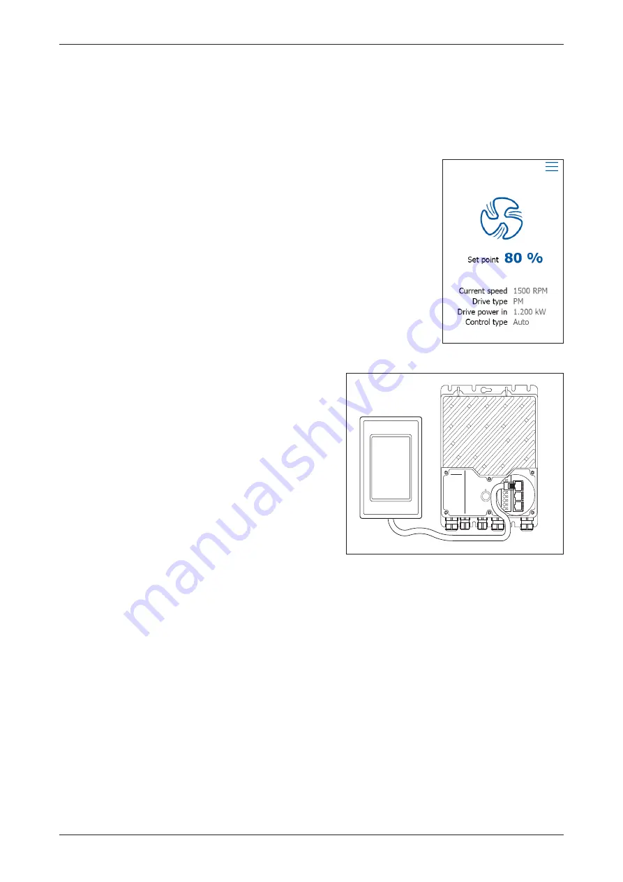
active, simply touch the screen once to open the home screen. The home
screen provides access to basic functions such as fan speed, drive type, drive
input power and control type. Any alarm or warning is shown at the top of the
screen. An alarm bell will be visible if an alarm has been activated. A warning
sign will be visible if there is an active warning. Press either the alarm bell or
warning sign to navigate to the alarm/warning list.
Press “Set point” or the setpoint value on the home screen to change the
setpoint value.
The ventilator icon shows if the fan is running or if it has been stopped. Press
the fan icon on the home screen to start or stop the fan motor.
Active & passive connection
The OJ-DV-HMI-35T comes with a Modbus cable with two RJ12/6 plugs on
each end, used to connect to the OJ-DV. See fig 2.1.
Active mode
When connected to the OJ-DV’s Modbus port “A”, the
OJ-DV-HMI-35T will function as a Modbus Master. Other
forms of Modbus Masters, such as OJ Air2 or BMS
controls cannot be connected at the same time.
Passive mode
Connected to Modbus OJ DV’s port ”C”, the OJ-DV-HMI-
35T will become a Modbus Slave. The hand terminal
can now be used in conjunction with other Modbus
communications using the OJ-DV’s ports “A”, “B” or the
spring terminals A, B and GND.
The OJ-DV-HMI-35T will then work as a “passive” display
for the OJ-DV, from which actual status and values can be
read, while the OJ-DV’s operation is controlled from the Modbus Master connected to ports “A”, “B” or the
spring terminals A, B and GND.
If, whilst connected to port “C”, there is a Modbus Timeout, to ports “A”, “B” or the spring terminals A, B
and GND, the OJ-DV-HMI-35T will automatically switch from a “passive” to “active” controller of the OJ-DV.
If the Modbus communication is reestablished to ports “A”, “B” or the spring terminals A, B and GND, the
OJ-DV-HMI-35T will automatically switch back from an “active” to a “passive” controller.
Figure 2.1
BR1014A1
1b
© 2019 OJ Electronic
A/
S
-V+
-Add. Pin2
-Bus B
-Bus A
-Gnd
-Add. Pin2
-Add. Pin2
-Bus B
-Bus A
-Gnd
-Add. Pin2
-V+
-Gnd
-Bus B
-Bus A
-Gnd
-V+
A
C
B
-
BR1014A11c
QUICK START GUIDE OJ-DV-HMI-35T


