background image

Contents

1.

Before use 

-----------


2.

Operating Precautions 

------


3.

Component name 

--------


4.

Installation

-----------


5.

Basic Operations


-------9

6.

Adjustments

----------12

7.

Maintenance

-------------19

8.

Trouble shooting 

-----------22

9.

Specifications

------------24

10

Warranty 

--------------


25

11

External dimensions 

---------


26

1. Before use

Thank you very much for purchasing our Automatic Screw Feeder, 

『BS-CS

 series

.

Please check up the escaperories supplied with it before using it.

 Accessories            Shoot box  x1         I/F cable x1           Operation manual x1       AC adapter x1      Allen wrench x1    

                                Screwdriver x1       Screw delivery tubex1


Before using your product, please read this manual carefully to get best results from the product.

2.

Operating Precautions

- 1 -


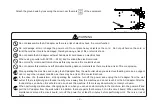
This manual contains safety alert symbols and safety precaution messages to prevent injuries of the operator or damages to property.


 Indications 

This indicates there is a chance of death, serious injury or fire 

 if the instructions are not followed.

This indicates there is a chance of personal injury or damage to property 

 if the instructions are not followed.

WARNING

CAUTION

 Symbols indicating type of danger and preventative measures

This indicates to stop operations.

Unplug power supply from wall outlet.

General caution.

Prohibited operation. Never do this!

Do not disassemble, modify or repair.

Do not touch with wet hands.

Summary of Contents for BS-C Series

Page 1: ...iated with our company We do not have any branches in China 自動ネジ供給機 BS CSeries Automatic Screw Feeder BCSMAE01 Operation Manual Maintenace Read these instructions for the proper use of this machine After having read these instructions keep them in a covenient place so you or the operator can refer to them whenever necessary ...

Page 2: ...product please read this manual carefully to get best results from the product 2 Operating Precautions 1 This manual contains safety alert symbols and safety precaution messages to prevent injuries of the operator or damages to property Indications This indicates there is a chance of death serious injury or fire if the instructions are not followed This indicates there is a chance of personal inju...

Page 3: ...ent odor or any other unusual condition as there may be a risk of fire or electric shock In the case of a thunderstorm stop operating the machine turn off the power and unplug the AC adapter from the wall outlet If there is lightning and thunder nearby move away from the machine and do not touch it or the AC adapter After the thunder stops and when it is safe to do do so check the machine If there...

Page 4: ...ay fall causing damage or injury When moving the machine always disconnect the AC adapter from the wall outlet or it may result in damage to the cord or cause a fire or electric shock Turn off the machine and unplug the AC adapter from the wall outlet during closing hours or if the machine will be unused for any extended period of time Do not operate this machine in overly humid or dusty condition...

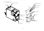
Page 5: ... ኚ ྕ ᖺ ኚ 3 Component name DC jack 4 I F cable Screw outer port LED indicater light Amplitude volume Feeding activation switch Air regulator Top lid Frequency volume Timer volume Airtube connection port for φ 6 tube ...

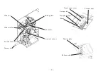
Page 6: ...Slide unit Rail sensor Screw out sensor Slide cylinder Screw exit Holding plate 5 Passing plate Rear hopper cover Rail assembly Air inlet connector Scraper right Scraper left Scooping hopper Brush ...

Page 7: ... ୖ ᮦ ᣦ Unloading complete LED Power switch Operation panel Unloading lever I F connector 6 Unloading lever open sensor Screw count sensor Unloading lever close sensor Unloading lever With the left side cover removed Screw delivery tube ...

Page 8: ...OUNT Displays the number of screws sent to the shoot box from the start of operation to the present When the number of screws sent reaches the set number the SCREW COUNT dot lights up and FINISH blue flashes At the same time the LED at the top of the shoot box also blinks If the number of screws sent exceeds the set number the value will blink WAITING LED yellow Turns on when the screw feeder is i...

Page 9: ...to the tube inlet on the top Be careful when routing the tube as sharp bending or strong tightening with a cable tie can cause screw clogging DC jack Air inlet screw delivery tube I F cable 4 Installation 4 1 Installation of the shoot box Φ28 metal joint mounting bracket is attached to the back of the shoot box It can be attached to a φ28 ejector pipe Also if you remove this mounting bracket you c...

Page 10: ...t the amount of screws accordingly depending on the actual operating rate and conditions of screw delivery flow Use only the adapter supplied with this machine to connect it to a wall outlet When you turn the power on the LED for the power lights up the motor rotates and screws are scooped on to the rail The rail vibrates to deliver screws to the pick up spot When the screws come to the stopper th...

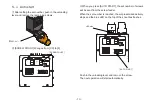
Page 11: ...op of the shoot box flashes Push in the unloading lever and remove the screw The next operation will start automatically 5 4 Auto start After setting the set number push in the unloading lever and remove the remaining screws SCREW COUNT changes from CC to 0 ᰴᘧ ࠉ Ṋ ࣝ ࢺᕤᴗ ᅗ 㸿㸱 ᢎ ㄆ ᅗ 〇 ᅗ タ ィ ኚ ྕ ᖺ ኚࠉ ࠉグࠉ ᢎㄆ ኚ సࠉᡂࠉᖺࠉ ࠉ B㸯㸳㹱 సᴗෆᐜ 〇ရྡ 㸦㒊ရྡ㸧 6 5 㸸 LED blue AUTO START SCREW COUNT 取出しレバー ...

Page 12: ...External Output 設定数5の場合 When the number of settings is 5 If the screw is not supplied to the tip of the rail for a certain period of time the vibration of the rail will increase The vibration of the rail is increased regularly in order to eliminate the biting of the screws in the scooping chamber The vibration noise becomes stronger but this is not a malfunction 5 5 Forced vibration of rail 5 6 In...

Page 13: ... VOL Adjust where screw flows fastest Around the middle Step3 If the vibration is too strong decrease the amplitude Use the supplied resin driver VOL may be damaged If the vibration is adjusted to a too large a value to increase the transport speed screws may jump from the rail and fall into the machine from the clearance failing to unload screws normally Adjust the vibration to a proper value tha...

Page 14: ...cted by optical sensors The timer volume is shown as picture below Third from the top Turning the volume clockwise will make the timer shorter and counter clockwise will make it longer Timer adjusting knob CW Shorter CCW Longer 6 3 Adjustment of the air pressurizing speed If the air pressure is set more than necessary amount the screw may bounce out from the output port Or when the pressure is too...

Page 15: ...ustment of the slide unit Speed controller for front Speed controller for back 6 5 Speed adjustment of the push cylinder If you need to adjust the speed of the push cylinder open the front cover and adjust with the speed controller After the adjustment is done please fasten the fixing nut firmly and reinstall the acrylic cover CW Less air slower CCW More air faster సᴗෆᐜ 〇ရྡ 㸦㒊ရྡ㸧 Push cylinder spe...

Page 16: ... low to affect vibration of the rail or too high so that screws became stuck within the opening When adjustment is necessary please loosen the screws and adjust the height of the cover 15 6 8 Adjustment of the scrapers Check that the clearances between the scraper right left and hopper wall right left are around 0 5mm When the scraper makes contact with the hopper wall the rail vibration becomes w...

Page 17: ...assing plate adjustment ᅗ ᢎ 〇 タ ኚ ྕ ᖺ ኚࠉ ࠉグࠉ ᢎㄆ ኚ సࠉᡂࠉᖺࠉ ࠉ సᴗෆᐜ 〇ရྡ 㸦㒊ရྡ㸧 〇ရྡ Holding plate Loaded screw Passing plate Passing plate fixing screw Passing plate The space between the passing plate and the screw shall be roughly 1 mm Opening on both side of the screw shall be even If the passing plate is too low screws cannot pass If the passing plate is too high it will hamper a smooth transport of...

Page 18: ...stment Remove both side covers front cover rail screw sensor mounting bracket and holding plate and check the positions of the rail and slide block grooves from above the machine Check the center position of the groove of the rail and slide block Visually make it almost in the center Check the height of the rail and slide block Lower the upper surface of the rail and the screw receiving part of th...

Page 19: ...lly check the height direction with the height adjustment nut so that the upper surface of the rail and the slide block screw receiving part are about 0 2 mm lower on the slide block side After adjustment fix it with the three slide unit fixing screws ᰴᘧ ࠉ ᅗ 㸱 ᢎ ㄆ ᅗ 〇 ᅗ タ ィ ኚ ྕ ᖺ ኚࠉ ࠉグࠉ సࠉᡂࠉᖺࠉ ࠉ B㸯㸳㹱 Height adjustment nut 6 9 5 Rail and Slide block adjustment Remove the holding plate temporary to ...

Page 20: ...e machine with air to remove iron powder and dust Also wipe the inside of the machine with a clean thin cloth soaked with alcohol Grease is applied to the following drive parts Check once a month and if there is a shortage of grease add grease Brush Drive Shaft Brush Drive Gear Large Brush Shaft CP Brush Gear Magnet Shaft Slide Block Unloading Lever Guide Recommended grease Made by Toray Dou Coati...

Page 21: ...gnet Shaft Slide Block 20 Grease application point on the brush drive gear large Grease application point on the magnet shaft Grease application point on the brush gear Grease application location Sliding part between magnet shaft and magnet arm Grease application method Remove the C ring and magnet arm and apply grease Grease application location Sliding part of slide block bush and slide shaft G...

Page 22: ... sweep screws off of the rail replace it Remove the brush assembly fixing screws and remove the brush assembly Assemble the new brush assembly in the reverse order Adjustment See 6 6 The part number of the brush assembly is PBSB4023 21 7 6 Confirmation of component interference in the event of abnormal vibration If you cannot adjust the vibration to the proper level check the following Interferenc...

Page 23: ...eaken the vibration Shorten the timer to reduce the amount of screws that ride on the scraper Raise the passing plate When the misaligned screws are caught on the passing plate Lower the passing plate Lower the brush Air pressurized delivery continues Intermittently Air pressurized delivery of screw abnormality It occurs when the screw count sensor of the shoot box cannot detect the screw in the a...

Page 24: ...contact us Slide unit does not move Abnormal screw outer sensor The screw outer sensor may be detecting the screw at all times A dust may have adhered to the surface or slit of the screw output sensor Remove the sensor and remove a dust adhering to the sensor surface and slits When assembling insert the slit on the light receiving side the sensor surface is black Air pressurized delivery is perfor...

Page 25: ...liance standard EMC 2014 30 EU MD 2006 42 EC RoHS2 2011 65 EU CAUTION This machine is a dedicated machine for the specified screw Please contact us when changing the screw type For improvement the design performance and specifications are subject to change without prior notice The noise of this unit is less than LAeq 70 dB at a distance of 1 m This product complies with EC directive Please check t...

Page 26: ...owing cases the purchaser shall pay for parts and labor regardless of the terms of warranty Failure due to improper handling Failure due to product modification or improper processing Failure due to causes beyond control for example earthquake or fire Failure attributable to any cause other than this product Consumable brushes main motor driving belt scraper And replaceable parts and replacement w...

Page 27: ...㺐㺻㺞㺎㺪㺈㺐㺛㺗㺎㺪㺼㺷 㺐㺸㺖㺞㺎ȭ ྲྀ 㔠ල ྲྀฟࡋ㺸㺨㺼㺎 ᙉไᅽ 㺛㺐㺍㺟 ༢ PP 㺦㺚㺼ᢞධཱྀ 11 External dimensions 26 Unit mm Power switch Shoot box Screw inlet I F cable DC jack Feeding activation switch Air regulator Screw outer port Screw inlet port Unloading lever Screw feeder I F cable Mount blacket for φ 28pipe ...

Page 28: ...aw この取扱説明書の一部または全部の無断転載 複製を禁じます Copyright OHTAKE ROOT KOGYO CO LTD 岩手県一関市萩荘字金ヶ崎27 021 0902 Tel 0191 24 3144 Fax 0191 24 3145 27 Kangasaki Hagisyou Ichinoseki Iwate 021 0902 JAPAN Tel 81 191 24 3144 Fax 81 191 24 3145 http www ohtake root co jp as of Dec 2020 2020年 12月現在 27 Kanegasaki Hagisyou Ichinoseki Iwate 021 0902 JAPAN Tel 81 191 24 3144 Fax 81 191 24 3145 岩手県一関市萩荘字金ヶ崎 27 021 0902 Tel 81 191 ...

Reviews: