


v1.0 Mar 2018
4
Ohmite FSP Series Integration Guide: Force Sensing Potentiometer
Integration Guide
Force Sensing Potentiometer
2 FSP01CE/FSP02CE Introduction
Ohmite's FSP01CE & FSP02CE Force Sensing Potentiometers (FSPs) are high-feature-set, cost-effective touch sensors
enabling intuitive control and navigation. FSPs are “single touch” devices that simultaneously report both touch
position and variable force. They are easy to integrate, high resolution, low-power, and ideal for a wide range of HMI/
MMI applications & markets. Interfacing is simple via a host processor without the need for a dedicated MCU. FSPs are
dynamically reconfi gurable in fi rmware enabling multiple functions from a single sensor.
3 FSP01CE/FSP02CE Construction
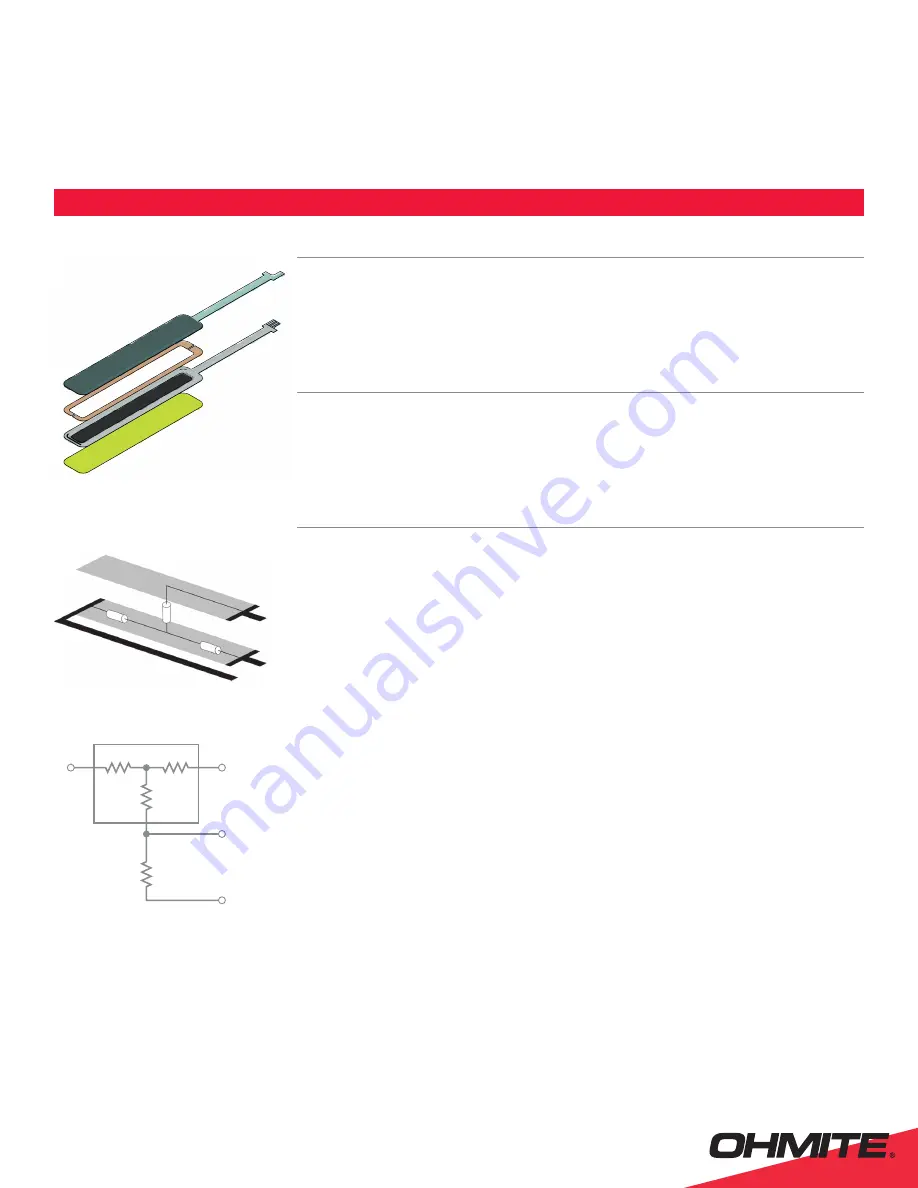
Force-Sensing Resistor (FSR) construction can generally be categorized into two types, Shunt Mode or Thru Mode*.
These alternate types exhibit different Force vs. Resistance characteristics. Ohmite's FSP01CE and FSP02CE are based
on Thru mode sensor construction which has solid top and bottom electrodes both over-printed with an FSR layer.
Current passes through the FSR ink from one layer to the other requiring electrical connections on both top and bottom
layers. (See Figure 1.)
4 FSP01CE/FSP02CE Connection and Sampling
Figure 2 shows the general resistance groups in a Force Sensing Potentiometer (FSP). R
1
+ R
2
is the total resistance
of the resistive layer on the Sensor while R
W
is the Force resistance between the conductive and resistive layer when
force is applied on the Sensor. The actual values of R
1
and R
2
depend on the location along the length of the Sensor
where the force is applied.
Figure 3 shows the general schematic for how the FSP can be setup for measuring the force being applied to it.
For best results, a microcontroller with an analog to digital converter (ADC) module should be used to measure the
position and relative force of touch along the length of the sensor.
The pins shown in Figure 3 need to be connected to the microcontroller as follows:
• V
1
– Digital pin
• V
2
– ADC pin
• V
WIPER
– ADC pin
• V
REF_NEG
– Digital pin
4.1 Position Measurement
The position of the touch location can be measured similarly to measuring the position of a standard potentiometer.
• Set all lines to 0 Volts to clear any existing charge from the sensor and reduce any noise on the readings
• Setup V
1
as an output pin on the microcontroller and make it output a digital HIGH signal.
• Setup V
2
as an output pin on the microcontroller and make it output a digital LOW signal.
• V
REF_NEG
must be setup as an input pin on the microcontroller and set to LOW (this ensures that no current fl ows
through R
REF
) and drains any further charge due to setting the other pins
• Setup V
WIPER
as an input pin (which ensures that no current fl ows through R
W
) and wait a few microseconds then take
an ADC measurement, A
POS
, from the pin. A
POS
represents the voltage across R
2
which will be directly proportional to the
position of the touch.
A second reading with V
1
set to LOW and V
2
set to HIGH can be taken to check the validity of the fi rst reading. The second
reading should be roughly equal to the bit count of the ADC - A
POS
For very light touches R
W
may have a high resistance of 500 Kohms or more therefore depending on the input resistance
of the ADC a high impedance buffer may improve positional measurement accuracy.
Figure 1.
Linear Sensor Structure
Figure 2.
Resistance groups on an FSLP
R
1
R
2
R
W
V
WIPER
V
2
V
1
Figure 3.
Force measurement setup schematic
V2
VWIPER
VREF_NEG
R2
RW
R1
V1
*
Further details on FSR types can be found in Ohmite's FSR Integration Guide at
www.ohmite.com
FSP01CE
Stacked view
A
Top layer
B
Spacer Adhesive
C
Bottom layer
D
Mount adhesive
A
B
C
D


