background image

Instructions

Each page is a step in constructing 

Ohbot

The parts needed are shown on the 

top left of each page

If you need tools it will show this too 

The main picture or pictures show how 

to assemble

2

Look out for 

my tips too!

Summary of Contents for v2.1

Page 1: ...Making Instructions Part 1 Ohbot Ltd 2021 For Ohbot v2 1 all platforms ...

Page 2: ...Each page is a step in constructing Ohbot The parts needed are shown on the top left of each page If you need tools it will show this too The main picture or pictures show how to assemble 2 Look out for my tips too ...

Page 3: ...3 underside of base Nice work I don t want to brag but Ohbots do have two more feet than you do Feet ...

Page 4: ...facing toward you Ohbot sticker 2 Thread the motor s cable through the big hole on the top of the base then put the motor in so that the writing on the label is the right way up This motor allows me to shake my head No really it does Neck turn motor ...

Page 5: ...back 1 Attach the motor to the base using the cable tie shown in green 4 Chop off the end of the cable tie 3 Attach the motor to the base using the cable tie Don t chop your finger off while cutting the ties Just saying Fixing the neck turn motor ...

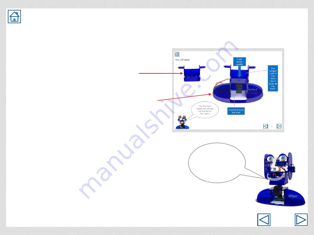
Page 6: ...6 Push down Attaching the neck ...

Page 7: ...o the front Gently turn the neck piece clockwise as far as it will go 2 Lift off the neck piece 3 Orient the neck piece in the position shown then push it back onto the motor 4 Screw the neck piece onto the motor front Ohbot sticker Setting up the neck turn motor ...

Page 8: ...ke sure the wires come out of the motors on the curved side of the jaw and go underneath the bottom lip motor Label the wires for the top and bottom lip to make them easier to identify later Bottom lip motor Top lip motor Attaching lip motors ...

Page 9: ...cable through the hole top 3 Clip the motor in place Fixing left cheek motor top It s easy to muddle right and left cheeks later Why not label this one Ohbot s lovely left cheek so you can find it later 2 Push the motor through at an angle starting with the end of the motor where the cable comes out ...

Page 10: ...ld be at the top 1 Orient the motor this way round with the wire coming out of the motor to the top of the cheek top top top This motor allows me to roll my eyes I know it s not polite but Ohbots only do what they are programmed to do Fixing right cheek motor ...

Page 11: ...11 Attach the left cheek to the jaw 1 Locate the lugs of the jaw in the slots on the cheek 2 Fasten the screw lugs slots left cheek ...

Page 12: ...12 1 Locate the pin on the neck in the hole in the left cheek 2 Hold in place ready for the next step pin hole Locating the jaw and cheek on the neck ...

Page 13: ...13 Attaching the right cheek to the jaw ...

Page 14: ...14 1 Use screw to fasten the right cheek to the neck 2 Do the same for the left cheek Fixing the cheeks to the neck ...

Page 15: ...n use the motor to push the clips apart Find the end of the motor where the wire comes out and push this through the hole first If it is tricky try taking the sticker off the motor Place the motor so that the motor shaft is on the opposite side to the posts clip clip ...

Page 16: ...16 underneath motor shaft Lid blink motor cable Fixing the lid blink motor Make sure the cables for both the eye turn motor and the lid blink motor come out on the same side Eye turn motor cable ...

Page 17: ...17 arm eyebox arm hole hole pin pin link Thread the link through this hole before clipping in the eyelid link Attaching the eyelids ...

Page 18: ...18 Attachng the eyeballs If you find one of Ohbot s eyes is looking up and the other one down turn one of the eyeballs up the other way down up turn upside down level ...

Page 19: ...19 hole hole pin pin 1 Put the pins for the eyebox into the holes shown on the cheeks 2 Use screws to attach each cheek to the eyebox Attaching eyebox to the cheeks ...

Page 20: ...20 Nose fitting ...

Page 21: ... marked Brown on this side 4 Yellow on this side 3 Attach the socket to the pins marked D4 Make sure the brown wire is to the left and the yellow wire is to the right S 2 On the Ohbrain board locate the set of pins marked D4 4 Connecting motor 4 to Ohbrain ...

Page 22: ...ed this way 4 6 7 8 5 10 9 Find the socket for each motor in turn and plug it into the matching D numbered pins on the Ohbrain circuit board Motor 5 goes to D5 Motor 6 to D6 Motor 7 to D7 Motor 8 to D8 Motor 9 to D9 and Motor 10 to D10 8 Connecting motors to Ohbrain ...

Page 23: ...23 Back of base C C C Fixing Ohbrain to the base Don t do these up too tight just tighten enough to stop the board being wobbly C C C ...

Page 24: ...24 Connecting the cable to Ohbrain ...

Page 25: ...plete Ohbot Before continuing to Part 2 of assembly please install software This is needed to set up the servo motors correctly Please go to www ohbot co uk Get Started Ohbot Kit Install Software Follow the instructions to install Install Ohbot software ...

Reviews: