background image


Ranger 7000

®

 Series Service Manual 

35 

Ohaus Corporation  www.ohaus.com 


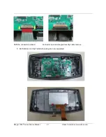
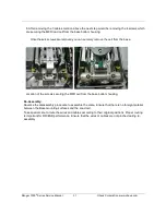
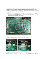
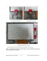
C)  Removing the 2 screws securing the RS232 Port to the bottom housing. 


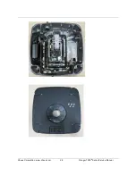
R71 RS232 port located behind the Terminal. 


2 screws securing the RS232 port against the Terminal housing removed. 

(Remember to place back these 2 screws after repairing) 


Summary of Contents for Ranger 7000 R71MHD3

Page 1: ...Ranger 7000 Scale Service Manual...

Page 2: ......

Page 3: ...ousing 18 3 4 OPENING THE BASE MODULE 22 3 4 1 Opening R71 large housing model 22 3 4 2 Opening R71 small housing mode 25 3 5 Replacing MFR Load cell R71 29 3 6 Replacing SG Load cell R71 32 3 7 REPLA...

Page 4: ...election 81 B 2 Product Selection 82 B 3 To Restore the EEPROM Data 82 B 4 Com Port Configuration 84 B 5 To Replace Load Cell 85 B 6 Install New Main Printed Circuit Board PCBA 87 B 7 Update the Softw...

Page 5: ...TABLE OF CONTENTS Ohaus Corporation www ohaus com iii Ranger 7000 Service Manual...

Page 6: ...asses an operational test segment display test performance tests and adjustments Chapter 5 Drawings and Parts Lists Contains exploded views of Ranger 7000 scales identifying all serviceable components...

Page 7: ...es The specifications for the approved scales below are only for initial testing These scales must be tested according to the requirements of the local Weights and Measures authority Before returning...

Page 8: ...Parts Counting Percent Weighing Check Weighing Dynamic Weighing Filling Formulation Differential Weighing Density Stabilization time typical Within 1 second Display TFT Graphic LCD Display size 4 3 i...

Page 9: ...ent Weighing Check Weighing Dynamic Weighing Filling Formulation Differential Weighing Density Stabilization time typical Within 1 second Display TFT Graphic LCD Display size 4 3 in Backlight White LE...

Page 10: ...Ohaus Corporation www ohaus com 8 Ranger 7000 Series Service Manual 1 5 OPERATION 1 5 1 Overview of the Controls...

Page 11: ...Ranger 7000 Series Service Manual 9 Ohaus Corporation www ohaus com...

Page 12: ...Ohaus Corporation www ohaus com 10 Ranger 7000 Series Service Manual 1 5 2 Principle Functions and Main Menu 1 2 Menu and Screen Navigation...

Page 13: ...edies in order Note Allow equipment to warm up for 60 minutes on precision models for optimal weighing performance Allow 4 hours for analytical models to stabilize 2 2 SOFTWARE In most cases understan...

Page 14: ...ror Tare out of range Error Tared at one unit but after switching to another unit the tare value exceeds the maximum Display Overflow Display Overflow Weight exceeds 6 digits No Calibration Calibratio...

Page 15: ...d remedies in the order they appear 4 Perform the indicated checks or see the appropriate section of the manual 5 Repair or replace the defective section of the scale NOTE If more than one symptom is...

Page 16: ...hich is at a different temperature than the area where it is to be operated Allow one hour for each 5 F 2 7 C temperature change before using the scale After temperature stabilization allow an additio...

Page 17: ...ration for Opening Ranger 7000 Models 1 Turn the scale off and unplug the power cord before you begin 2 Disconnect any communication or other option cables 3 3 OPENING THE TERMINAL MODULE Below show a...

Page 18: ...ation www ohaus com 16 Ranger 7000 Series Service Manual 3 3 2 Detaching the base RS422 cable from the Terminal 1 Dismantle the base RS422 cable from the Terminal 2 Removing the docking bracket from t...

Page 19: ...ual 17 Ohaus Corporation www ohaus com 3 Flip the Terminal around locate the 3 screws as shown and remove the screws which are mounting the bracket to the Terminal as shown below and separate the dock...

Page 20: ...e Manual 3 3 3 Dismantling the Terminal housing 1 Remove the 5 screws securing the housing 4 screws are located underneath the rubber cover at 4 corners of the bottom housing Remove the rubber cover a...

Page 21: ...ng the bottom housing with the top housing turn the terminal module over After that carefully lift up the top housing DO NOT remove the top housing completely away from the bottom housing because the...

Page 22: ...thin screw driver blade radiated the back cable lock on the connector 90 so that it is perpendicular to the cable as show in below pictures Connector lock with ribbon cable attaches Connector open wi...

Page 23: ...Ranger 7000 Series Service Manual 21 Ohaus Corporation www ohaus com Shift the connector outward Connector open and keypad overlay cable remove 5 Both bottom and top Terminal housing are now separated...

Page 24: ...ng model R71MD15 R71MD35 R71MHD15 R71MHD35 A R71MD15 is used in below 1 Prepare the bases as mention above 2 Remove the weighing Pan from the base Complete set of Large Housing base Weighing pan remov...

Page 25: ...nger 7000 Series Service Manual 23 Ohaus Corporation www ohaus com Spider removed from base top housing 4 Remove 6 screws securing the base top housing and bottom housing Location of the first 6 screw...

Page 26: ...Service Manual 5 The 7th screw is underneath the LFT cover Remove the 2 screws securing the LFT cover 7th screw expose by removing this screw you will be able to dismantle the base top housing from th...

Page 27: ...Opening R71 small housing model R71MHD6 is used in below 6 Prepare the bases as mention above 7 Remove the weighing Pan and Wind Ring from the base Complete set of MFR base Weighing pan removed Wind...

Page 28: ...www ohaus com 26 Ranger 7000 Series Service Manual Location of 2 screws securing the Spider with base top housing Spider removed from base top housing 9 Remove 5 screws securing the base top housing a...

Page 29: ...haus Corporation www ohaus com 10 The 5th screw is underneath the LFT cover Remove the 2 screws securing the LFT cover 5th screw expose by removing this screw you will be able to dismantle the base to...

Page 30: ...Ohaus Corporation www ohaus com 28 Ranger 7000 Series Service Manual...

Page 31: ...d cell R71 Model R71MHD6 is shown below 1 Locate the 4 screws securing the MFR load cell with the base bottom housing R71 load cell type MFR 3 Remove the cable connecting the Base PCBA with MFR load c...

Page 32: ...Ohaus Corporation www ohaus com 30 Ranger 7000 Series Service Manual 5 Remove the cable connected from the load cell Auto Calibration motor PCBA to the main PCBA as shown below...

Page 33: ...remove the cell from the base Location of the screws securing the MFR cell from the base bottom housing Re Assembly Reverse the disassembly procedure to assemble the scale Ensure that there is no for...

Page 34: ...s Service Manual 3 6 Replacing SG Load cell R71 Model R71MD15 is shown below 1 Locate the 2 screws securing the SG load cell with the base bottom housing R71 load cell type SG 2 Remove the cable conne...

Page 35: ...the base housing Re Assembly Reverse the disassembly procedure to assemble the scale Ensure that there is no foreign material between the Base mounting surfaces and the Load cell Take special care to...

Page 36: ...ve mat with wrist straps be used when working with electronic components 3 7 1 Terminal A Separate the Terminal PCBA from the bottom housing by removing 4 screws one 8PIN connector on top of the PCBA...

Page 37: ...n www ohaus com C Removing the 2 screws securing the RS232 Port to the bottom housing R71 RS232 port located behind the Terminal 2 screws securing the RS232 port against the Terminal housing removed R...

Page 38: ...l Terminal PCBA taken out from Terminal bottom housing 3 7 2 Remove the TFT PCB A Remove the two screws holding the TFT in place as shown below Location of the 2 screws holding the TFT in place agains...

Page 39: ...t RED holder position Wrong RED holder position 2 screws and Red Holder removed B Gently remove the TFT from the top housing and place in a secure area When re installing the TFT PCB make sure the sur...

Page 40: ...Ohaus Corporation www ohaus com 38 Ranger 7000 Series Service Manual TFT PCB removed from Terminal Top housing R71 4 3 TFT Display PCB P N 30095940...

Page 41: ...oosen the 2 screws securing the main PCBA with the base bottom housing 1 Remove the below cables from the main PCBA Location of the 5 cables on the main PCBA A Cable Red Black Cable from main PCBA to...

Page 42: ...locate and loosen 2 screws which securing the LFT PCBA to the bottom housing Location of the 2 screws securing the main PCBA to the bottom housing Screw at Lock position Screw at Un Lock position Once...

Page 43: ...en the 2 screws securing the LFT PCBA with the base bottom housing 1 Remove the below 5 cables from the LFT PCBA Location for the 5 cables A Cable Cable link from LFT PCBA to optional rechargeable bat...

Page 44: ...les now locate and loosen 2 screws which securing the LFT PCBA to the bottom housing Picture shows 5 cables removed location of the 2 screws Screw at Lock position Screw at Un Lock position Once you s...

Page 45: ...e 2 screws securing the LFT PCBA with the base bottom housing 1 Remove the below 5 cables from the LFT PCBA Location for the 5 cables A Cable Cable link from LFT PCBA to optional rechargeable battery...

Page 46: ...les now locate and loosen 2 screws which securing the LFT PCBA to the bottom housing Picture shows 5 cables removed location of the 2 screws Screw at Lock position Screw at Un Lock position Once you s...

Page 47: ...oration www ohaus com 3 7 6 Replacing SG Main PCBA R71 R71MD3 R71MD6 R71MD15 R71MD35 Model R71MD15 is shown below 1 Remove 4 cables from the main PCBA 2 Remove the 3 screws securing the main PCBA with...

Page 48: ...Manual 1 Remove the below cables from the main PCBA Location for the 4 cables A Cable RS422 cable from main PCBA to R71 Display Terminal B Cable Cable link from main PCBA to LFT PCBA C Cable Red White...

Page 49: ...Ranger 7000 Series Service Manual 47 Ohaus Corporation www ohaus com 2 After removing the above 4 cables now locate and remove 3 screws which securing the main PCBA to the bottom housing...

Page 50: ...se tests The Analytical models need up to 4 hours to stabilize NOTE Make sure the test area is free from drafts and that the scale rests on a level and vibration free surface The Analytical models esp...

Page 51: ...of weight readings If the scale passes the precision test than the following tests should be performed Note This is a reference test for approved models OIML and NTEP It is not a required test but it...

Page 52: ...vice menu see Chapter 6 and adjust and record the following settings Set the Stability setting to 0 5d its lowest setting Set the Filter level to Middle Set the AZT Auto Zero Tracking to 5d its lowest...

Page 53: ...ding 7 Reading 8 Reading 9 Reading 10 10 Mean ________ 6 Calculate the Delta for each reading and record in the work sheet Delta Reading Mean 7 Calculate the Delta x Delta for each reading and record...

Page 54: ...uld be able to pass this test so it is still valid to determine scale performance NOTE The scale must pass the Precision and Repeatability Tests and be calibrated before the Linearity Test is performe...

Page 55: ...5 kg 3 kg smaller weights are used If weights cannot be stacked they R71MD6 0 kg 3 kg 6 kg must be placed uniformly over the segment R71MD15 0 kg 10 kg 15 kg R71MD35 0 kg 20 kg 35 kg The test position...

Page 56: ...Ohaus Corporation www ohaus com 54 Ranger 7000 Series Service Manual Note In high resolution scales Class I it may be necessary to zero or tare between each location...

Page 57: ...parated into separate sections for the Terminal and the Base To order spare parts identify the required item in the exploded views and parts list then use the Spare Parts List to obtain the current pa...

Page 58: ...Ohaus Corporation www ohaus com 56 Ranger 7000 Series Service Manual 5 1TERMINAL SPARE PARTS...

Page 59: ...1 TERMINAL SPARE PARTS Drawing Item Part Number Description 1 30095939 SP Overlay R71 Terminal 2 30095940 SP 4 3 TFT Display R71 Terminal 3 30095930 SP PCBA Terminal R71 4 30103748 SP 8PIN Connector T...

Page 60: ...Ohaus Corporation www ohaus com 58 Ranger 7000 Series Service Manual 5 2 BASE SPARE PARTS R71MD3 and R71MD6...

Page 61: ...SG Loadcell 5kg R71 7 30076250 SP PCBA LFT EX HiCap R71 8 30095909 SP PCBA Base SG R71 9 30041267 SP Power Cord US EX HiCap R71 30041462 SP Power Cord EU EX HiCap R71 30041463 SP Power Cord CN EX HiCa...

Page 62: ...Ohaus Corporation www ohaus com 60 Ranger 7000 Series Service Manual 5 3BASE SPARE PARTS R71MD15 and R71MD35...

Page 63: ...SG Loadcell 5kg R71 7 30076250 SP PCBA LFT EX HiCap R71 8 30095909 SP PCBA Base SG R71 9 30041267 SP Power Cord US EX HiCap R71 30041462 SP Power Cord EU EX HiCap R71 30041463 SP Power Cord CN EX HiC...

Page 64: ...Ohaus Corporation www ohaus com 62 Ranger 7000 Series Service Manual 5 4BASE SPARE PARTS R71MHD3 and R71MHD6...

Page 65: ...MFR Loadcell 4kg R71 7 30076250 SP PCBA LFT EX HiCap R71 8 30111916 SP PCBA Base MFR R71 9 30041267 SP Power Cord US EX HiCap R71 30041462 SP Power Cord EU EX HiCap R71 30041463 SP Power Cord CN EX H...

Page 66: ...Ohaus Corporation www ohaus com 64 Ranger 7000 Series Service Manual 5 5BASE SPARE PARTS R71MHD15 and R71MHD35...

Page 67: ...P MFR Loadcell 4kg R71 7 30076250 SP PCBA LFT EX HiCap R71 8 30111916 SP PCBA Base MFR R71 9 30041267 SP Power Cord US EX HiCap R71 30041462 SP Power Cord EU EX HiCap R71 30041463 SP Power Cord CN EX...

Page 68: ...r key during weighing mode you will be able to select the pre set User Profiles By keying the Super Password OHR71 you will be able to see Service Menu under Maintenance Diagnosis as shown below 1 Pre...

Page 69: ...press 0 User key this mean there is no user profile database been created and you need to create the user profile 2 Proceed to Menu and select User Profile 3 Start keying in your user profile informa...

Page 70: ...com After saving the information you will be able to see the User under User Profiles Now by following step 1 to 3 you will be able to gain access into Service Menu 5 Key in the Super password OHR71...

Page 71: ...Ohaus Corporation www ohaus com 69 Ranger 7000 Series Service Manual 6 Proceed to Main Menu and select Maintenance...

Page 72: ...e Menu 6 3 Under Service Menu 1 Under Service Menu you will have the below options RAMP value typical value range from 50 80 varies depends on models and value should not be 0 or 100 Expand For R and...

Page 73: ...nal firmware Note When downloading Terminal Software using Ohaus Repair and Service Tool the file is type mot If downloading via the USB host is type bin The software need to be put in the R71_FW fold...

Page 74: ...ble to see the below example information once you select the Firmware Update option If the USB Flash drive is not plug in you will see the below message Format Alibi Memory Formatting Erasing Alibi me...

Page 75: ...Ranger 7000 Series Service Manual 6 4Maintenance Diagnostic 1 Under Diagnostic you will have the below options LCD diagnostic 4 diagnostic test will be perform on the color LCD screen for RED Green B...

Page 76: ...Ranger 7000 Series Service Manual 74 Ohaus Corporation www ohaus com 4 key tests testing the functionality of the keypad membrane the below 4 keys will be tested during this diagnostic 75...

Page 77: ...Ohaus Corporation www ohaus com 75 Ranger 7000 Series Service Manual...

Page 78: ...Service Manual 76 Ohaus Corporation www ohaus com 6 5Disable Service Menu 1 Press and hold 0 User button you will see the preset User Profiles 2 By selecting the far right button you will come to the...

Page 79: ...Ohaus Corporation www ohaus com 77 Ranger 7000 Series Service Manual 3 Key in previously set User password example 123 you will disable the Service Menu as shown below...

Page 80: ...e used to communicate with the scale using commands that are listed at the end of the appendix The latest software service tool and support files are available on the Ohaus DMX site Please read the Se...

Page 81: ...A 3 USB Host The USB Host can be used to connect a barcode scanner and USB flash drive to the Ranger 7000 A 3 1 Printout Format A 3 2 Printout string for g kg lb oz units The printout string has a fix...

Page 82: ...mediate left of the most significant digit The Unit1 field is 2 left justified characters The Weight2 field is 7 right justified characters The Unit2 field is 2 left justified characters The Stability...

Page 83: ...s used for 5 purposes 1 To restore EEPROM data if there is any possible data corruption 2 To install a new Load Cell 3 To install a new Main Printed Circuit Board PCB 4 To update the software in the s...

Page 84: ...r from the label on the back of the scale c IDNR Number just above the label on the back of the scale d The load cell serial number you need to open the scale and record this information on the load c...

Page 85: ...Ohaus Corporation www ohaus com 83 Ranger 7000 Series Service Manual Figure B 3 Restore EEPROM Figure B 4 Write Image File...

Page 86: ...ure there is no lose connection from R71 RS232 Port during the communication process 2 Enter the scale s Serial Number and IDNR number 3 Enter the path to the image file or click the Browse button to...

Page 87: ...th the replacement Load Cell These labels each contain a model number followed by the IDNR number Carefully select the label that matches exactly the model number of the scale 9 Get the scale Image Fi...

Page 88: ...Loadcell 15 Configure the Com Port Configuration B 2 and click Next 16 Key in the scale serial number Model number Temperature Reference in Celsius and select your region AP EU GB or US 17 Enter the...

Page 89: ...of the scale then re connect 20 Perform Service Calibrations see Appendix B Test the scale B 6 Install New Main Printed Circuit Board PCBA 1 Follow steps in Sections 3 7 3 and 3 7 6 to replace the PCB...

Page 90: ...he scale 5 Enter the IDNR number xxx xx xx xxxx from the label on the back of the scale 6 Key in the Model number and Shipping Country AP EU GB or US 7 Click the Start button 8 The software will indic...

Page 91: ...ab labeled Download Software Figure B 11 Download Software Tab 4 You will have two options to choose Down load Base Software and Down load Terminal Software select the process you wish to perform B 12...

Page 92: ...he download process When complete disconnect the power from the back of the scale then re connect 9 Perform Service Calibrations see Chapter 6 Test the scale B 8 Diagnostics 1 Connect the scale to you...

Page 93: ...Ohaus Corporation www ohaus com 91 Ranger 7000 Series Service Manual Figure B 13 Diagnostics Command Testing...

Page 94: ...all rights reserved Registered trademark of Ohaus Corporation The information contained in this manual is believed to be accurate at the time of publication but Ohaus Corporation assumes no liability...

Reviews: