


CHAPTER 3 MAINTENANCE PROCEDURES
Ohaus Corporation www.ohaus.com
16
Navigator Series Service Manual
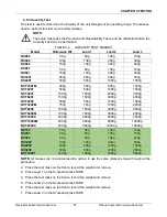
NVT models
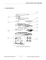
Figure 3-4
Position load cell, PCB and AC wires
5. To assemble the Housing, follow the steps in Section 3.2.1 in reverse order.
3.4 REPLACING THE PRINTED CIRCUIT BOARD AND DISPLAY
1. Open the scale
– see Section 3.2.
2. Pick the PCB off its mounting pins and position the PCB upside-down so that the load cell wire
connection is easy to access.
3. Disconnect the Load Cell cable from the PCB. The load cell connection is a five-wire cable
that is soldered directly to the PCB. Before disconnecting the cable record the wire colors and
their location on the PCB. (Hint: A digital picture is an easy and reliable record.) Disconnect
the cable connecting the PCB to the Load Cell by un-soldering the 5 wires from the PCB.
Take care not to over heat the PCB which will damage the thin PCB conductors.
4. Unsolder the AC Cable wires from the PCB.
5. Follow these steps in reverse order to install the new PCB.
6. Configure the Scale. (See Appendix C.)
Note:
The PCB and the LCD Display are supplied as a single unit. However, if only the LCD
Display needs replacement, it can be separated from the PCB by unsoldering the fine lead-wires
connecting it to the PCB. When installing the new LCD Display, carefully feed the lead-wires
through their holes, check that the new assembly is seated properly on the PCB and then solder the
lead-wires.
Position jack
Position PCB on
locating Pins
Route wires
Summary of Contents for Navigator Series
Page 1: ...SERVICE MANUAL NavigatorTM Series Scales...
Page 2: ......
Page 50: ......
Page 51: ......


