background image

40720
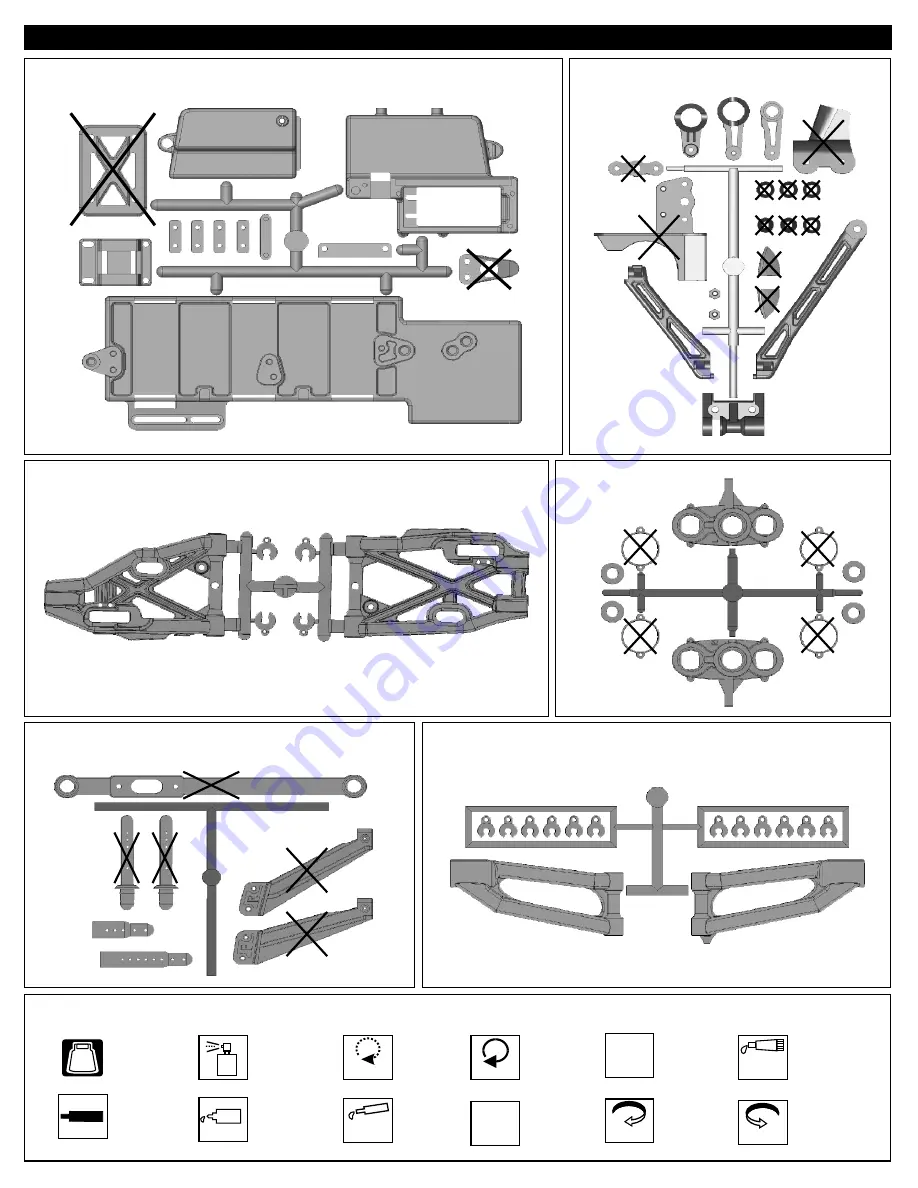
SIDE IMPACT BUMPER AND BODY POST 

40539
SERVO SAVER

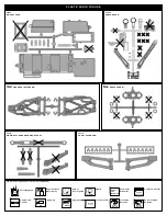
SYMBOL USED THROUGHOUT THE INSTRUCTION MANUAL

Ensure
Free
Movement

Ensure Free
Movement

Apply
Grease

Apply Grease

Oil

Tighten

Tighten

   Do Not
Over Tighten

  Rotate
Direction

  Rotate
Direction

  Contact
 Adhesive

  Contact  Adhesive

Screw 

Cement

BAG

1:1

Parts Bag Used

Degrease With
Motor Spray

Do Not 
Over Tighten

Clockwise 
Rotation

Anti-clockwise
Rotation

True-To-Scale

Apply Oil

Apply Screw 
Cement

40717  
FRONT AND REAR LOWER ARM

40718
FRONT KNUCKLE ARM

40716
FRONT UPPER ARM 

PLASTIC PARTS FOR USE

30662
BATTERY CASE

Summary of Contents for DM-ONE-SPEC e

Page 1: ......

Page 2: ......

Page 3: ...to drive it safely 3 Before Operating Make sure that all screws and nuts are properly tightened Radio Check battery life before running the car If the radio does not have full control of the car with steering and or throttle brake do not run until corrected Failure to correct this will result in possible injury and damage to the car or property Please confirm the neutral throttle trigger position ...

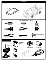
Page 4: ...ers Equipment Needed OVERVIEW Components Transmitter Parts Bag Receiver Radio Control Car UM 3 Batteries 8pcs Body Reamer Instant Cemment Screw Cement CA Screw Cement GEAR GREASE Gear Grease 7 4V Li Po Battery Hard Case L Battery Charger i Po Servo Brushless Motor Brushless Electric Speed Controller ...

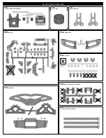
Page 5: ...BOX 40538 DIFF CASE 40040 CENTER DIFF MOUNT PLASTIC PARTS 40721 FRONT BUMPER 31304 REAR UPRIGHT 40643 SHOCK PLASTIC Parts for Not Use PLASTIC PARTS FOR USE 40719 40719 ARM HOLDER 40537 REAR UPPER ARM 30663 VELCRO BATTERY STRAPS ...

Page 6: ...n Tighten Do Not Over Tighten Rotate Direction Rotate Direction Contact Adhesive Contact Adhesive Screw Cement BAG 1 1 Parts Bag Used Degrease With Motor Spray Do Not Over Tighten Clockwise Rotation Anti clockwise Rotation True To Scale Apply Oil Apply Screw Cement 40717 FRONT AND REAR LOWER ARM 40718 FRONT KNUCKLE ARM 40716 FRONT UPPER ARM PLASTIC PARTS FOR USE 30662 BATTERY CASE ...

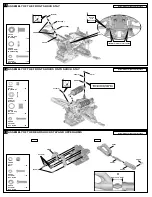
Page 7: ...to damage shock shaft Tighten 40643 40640 0 20 30 40 10 40633 40640 40090 40090 40090 2mm 40090 40090 1mm 40634 40632 Step 3 2 6x5mm 40638 2 6x5mm 30403 40643 Short 40054 40643 40090 2mm Washer 40090 1mm Washer 40090 3 5mm O Ring 40090 7mm R Ring Step 6 40060 40751 x4 x2 x2 x2 Step 2 Assemble 2 seets for rear Step 1 40090 2mm Washer 40090 1mm Washer 40090 3 5mm O Ring 40090 7mm R Ring x4 x2 x2 x2 ...

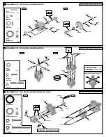
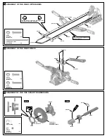
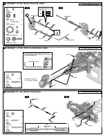
Page 8: ...OF THE FRONT AND REAR GEAR CASE 5x4mm 40519 40533 40024 36053 4x35mm 40024 40516 13T 36053 4x15mm 40533 40010 Put the Diff Oil 100000 for front and the 5000 for Rear Fill the Diff case to approx 80 with the Diff Oil 40513 30776 Step 1 Step 2 Step 1 Step 2 94020 3x12mm Flat Head Hex Screw x8 94015 4x35mm Hex Screw x4 94011 4x15mm Hex Screw x4 Tight the diff screws in this order 1 4 3 2 S r w c e Ce...

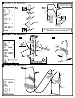
Page 9: ...ice the direction of the servo saver connecting plate 40719 x2 x2 40531 Shock Ball End Post 40531 3x25mm 40719 4x12mm x5 Step 1 Step 2 Step 1 Step 2 3mm 94003 3x10mm Hex Screw 90018 3x25mm Cap Screw 94026 4x12mm Flat Head Hex Screw x2 Tighten the steering plate hex screw all way down and then back it off 1 2 turn Ensure Free Movement Set the left and right hand side upper arm adjuster in the same ...

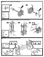
Page 10: ...AVER AND FRONT UPPER ARMS x2 40525 3x48 1mm Arm Shaft 40719 3x12mm 4x12mm 40716 1mm and 3mm 40716 2mm 40719 Step 2 40525 40525 94020 3x12mm Flat Head Hex Screw x2 94026 4x12mm Flat Head Hex Screw x4 94009 4x10mm Hex Screw x2 Insert the upper arm adjust into shock stay 40716 Step 1 Assemble both right and left side Step 2 Set the left and right hand side upper arms adjuster in the same direction Le...

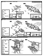
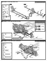
Page 11: ...ARMS 13 x2 36850 7mm Ball x2 x4 35958 5x8x2 5mm Ball Bearing 36742 Shock Cap Bushing 94005 3x15mm Hex Screw x2 94004 3x12mm Hex Screw x2 94010 4x12mm Hex Screw x4 Take the shock cap washer from the shock plastic tree Ensure Free Movement Do Not Over Tighten Do Not Over Tighten Step 2 11 G 36850 36861 40537 40065 Approx 12 5 mm Step 1 Assemble both right and left sides Assemble both right and left ...

Page 12: ...x2 40546 3x42 7mm Arm Shaft Set the left and right hand side upper arms adjuster in the same direction Left Right x1 94011 4x15mm Hex Screw x2 94010 4x12mm Hex Screw 16 40539 4x15mm ASSEMBLY OF THE ONE SPEED TRANSMISSION Step 1 Step 2 35247 47t 35248 48t 35249 49t Stock 35219 40760 5X4mm 40120 36053 40759 6mm 94036 5x4mm Set Screw x1 36743 6mm E Ring x1 S c r e w C e n t m e Clockwise Rotate Direc...

Page 13: ... 5x4mm 6mm S c r e w C e m e n t 40120 36053 Step 1 Step 2 x2 94034 4x4mm Set Screw 94003 3x10mm Hex Screw x4 40040 40040 40512 Step 3 3x10mm 40714 Do Not Over Tighten 40719 4x4mm 40719 Front Front 40719 4x16mm 40719 4x16mm 40719 Front Rear 40719 Rear Front 40719 Rear Rear set the arm holder adjuster to the same direction A A Type A x8 94027 4x16mm Flat Head Hex Screw set the arm holder adjuster t...

Page 14: ...WER ARMS 40711 4x10mm 3x18mm 3x8mm 40717 40719 31308 40719 4x10mm 3x18mm 40719 3x8mm 40717 31308 40719 Center Keep stabilizer ball in the center Turn stabilizer adjuster to adjust the stabilizer to the same angle Adjuster Assemble both right and left sides 2mm A 3x8mm set screw is use for tighten or loose stabilizer x2 94035 3x8mm Set Screw x2 36870 4x10mm Set Screw x2 94006 3x18mm Hex Screw ASSEM...

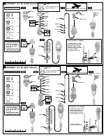
Page 15: ...stic washer 5mm Allen Wrench ASSEMBLY OF THE FRONT SUSPENSION ARMS Assemble both right and left sides 94005 3x15mm Flat Head Hex Screw 94041 3mm Nylon Nut x2 x2 3x15mm 40126 3mm Put the drive shaft into cap joint before assembly 2 5mm Allen Wrench When assembling the steering balls into the arms leave about two threads for the upper arm and leave no room for bottom arm ASSEMBLY OF THE FRONT PUSH R...

Page 16: ...REAR SUSPENSION ARMS x2 94041 3mm Nylon Nut x2 94008 3x25mm Hex Screw Assemble both right and left sides 3x25mm 3mm Insert the drive shaft before assembly 34028 2 5mm Allen Wrench When assembling the steering balls into the arms leave about one threads for the rear arm and leave no room for front arm Front Rear ASSEMBLY OF THE REAR SHOCK ABSORBER Assemble both right and left sides x2 94007 3x20mm ...

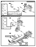
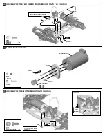
Page 17: ...ment 4x10mm 40762 90mm 40762 97mm MOTOR INSTALLATION x3 94019 3x10mm Flat Head Hex Screw ASSEMBLY OF THE MOTOR MOUNT ONTO CHASSIS 10114 5mm Engine Mount Screw x2 10114 Do Not Over Tighten Tighten the 10114 screw temporary Ensure Free Movement Step detail 3x10mm 4x4mm 41202 Motor Not Included 30664 13t stock 30665 14t 30666 15t 30667 16t 30668 17t x1 94034 4x4mm Set Screw Screw C ment e ...

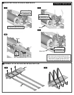
Page 18: ...et a perfect gear mesh place a piece of notebook paper between the gears and tighten the motor mount screws The spur gear may be damaged if the gear mesh is wrong 3mm Insert a notebook paper between spur gear and motor gear to make correct gear mesh PULL OUT ASSEMBLY OF THE VELCRO STRAP INTO BATTERY CASE 30662 30663 Step 1 Step 2 Notebook Paper Notebook Paper Notebook Paper ...

Page 19: ... tapes ASSEMBLY OF THE WIRE BRIDGE ONTO BATTERY CASE AND RECEIVER BOX 3x10mm 30662 30662 30662 3x8mm 94002 3x8mm Hex Screw x2 94003 3x10mm Hex Screw x2 ASSEMBLY OF THE ELECTRIC SPEED CONTROL WIRE INTO RADIO CASE Step 1 Step 2 Route the speed control wire as picture shown Route the speed control wire into receiver box ...

Page 20: ...x0 8mm 30662B 3x10mm 3x8x0 8mm ASSEMBLY OF THE STEERING SERVO WIRE INTO RADIO CASE Electric Speed Control Wire Steering Servo Wire Steering Servo Not Included ASSEMBLY OF THE RADIO CASE ONTO CHASSIS 3x10mm 4x10mm 3x10mm 4x12mm Step 2 Step 1 94026 4x12mm Flat Head Hex Screw x1 94019 3x10mm Flat Head Hex Screw x6 3x10mm ...

Page 21: ...nna Wire 41 42 ASSEMBLY OF THE STEERING ROD ONTO RADIO BOX Approx 16 6mm 94004 3x12mm Hex Screw x2 0 20 30 40 10 Step 2 Step 1 30411 37320 30401 30401 30411 3x12mm Use the screw provided with your servo 10769 30661 3x12mm 4x12mm ASSEMBLY OF THE FRONT BUMPER 40721 40721 94026 4x12mm Flat Head Hex Screw x3 x2 94020 3x12mm Flat Head Hex Screw 3x12mm Tighten Tighten 4mm x3 94042 4mm Nylon Nut Approx 3...

Page 22: ... Tighten ASSEMBLY OF THE FRONT BUMPER 94009 4x10mm Hex Screw x2 x2 94020 3x12mm Flat Head Hex Screw ASSEMBLY OF THE FRONT BUMPER 4x10mm 40725 3x12mm ASSEMBLY OF THE REAR BUMPER 40721 4x12mm 40721 94026 4x12mm Flat Head Hex Screw x2 x2 94020 3x12mm Flat Head Hex Screw x2 94042 4mm Nylon Nut Approx 28 5 mm 1 1 3x12mm 4mm Tighten 4x12mm 31159 31159 40117 Tighten Tighten Tighten Tighten ...

Page 23: ... 4x10mm Hex Screw x2 4x10mm 3x12mm 94004 3x12mm Hex Screw x2 ASSEMBLY OF THE REAR BUMPER The 4x10mm set screw is used to adjust down stop Approx 3 mm 48 40117 40720 40117 40720 BATTERY INSTALL Battery Not Included 8mm 15mm If use hard case battery make a hole as picture shown Follow the manual instruction sprovided by ESC manufacturer to install the wire Be aware of the direction of the battery Ha...

Page 24: ...tact Adhesive Contact Adhesive Contact Adhesive Notice the direction of the tires Make two the same for the left and 2 for the right Check the rotation direction before gluing Pull back the tire bead slightly and spot glue in four spots as shown When dry glue the rest of the wheel between the spots Repeat the procedure on the other side of the wheel until fully glued ASSEMBLY OF THE TIRES AND WHEE...

Page 25: ...assis to confirm the mounting position and location for holes Step 1 Step 2 Make 9mm holes on the body shell as shown Make 4mm holes Make 7mm holes Body Reamer not included Make a 7mm hole Make a 7mm hole Make 3mm holes Make 3mm hole Make 3mm holes Make 3mm hole Wing Side Plate L Wing Side Plate R Step 1 Step 2 The position and the wing is the same Hole Position Hole Position Hole Position ...

Page 26: ...ask the windows on the inside with masking tape Step 2 Paint the body with polycarbonate spray paints When you have finished painting peel off the external protective films When the paint is dry remove the masking ASSEMBLY OF THE WING ONTO THE BODY SHELL Step 1 Step 2 x4 94041 3mm Nylon Nut x4 94001 3x5mm Hex Screw 3mm 3x5mm Nylon Nut Nylon Nut Nylon Screw x2 x2 Nylon Nut ...

Page 27: ...58 MOUNTING THE BODY SHELL 31159 31159 ...

Page 28: ...e in Response will be under steer Making the 12mm ball shorter will make the rear tires toe out Response will be over steer We recommended adjusting the rear toe in to 2 degrees Use a 2 5mm allen wrench to adjust toe in for front and rear Front Rear Note Place the model car on a flat surface Raise the chassis to it s maximum clearance before the wheels leave the ground Adjust the length of the fro...

Page 29: ... 95 35958 BEARING 5X8mm 1 PC 3 95 40717 LOWER ARMS FRONT REAR DM 19 95 36053 BEARING 8x16mm PAIR 12 95 40718 STEERING KNUCKLE PIVOT BALL DM 19 95 36055 PIN 2 5x17mm HEX HUBS 4PCS 3 95 40719 ARM HOLDER PLASTIC DM 15 95 36082 REAR AXLES 8mm PAIR 10 95 40720 BUMPER SIDE BODY DM 9 95 36700 STEERING BALL END 7mm 8PCS 6 95 40721 BUMPER FRONT REAR DM 19 95 36742 BUSHING SERVO SAVER 1 95 40725 BUMPER FOAM...

Page 30: ......
Page 31: ... kit is incomplete or component parts are broken due to error in manufacturer contact your dealer from which you purchased the kit for replacement part or call OFNA at 949 586 2910 for your nearest dealer location Other items such as radio and engine other covered by individual warranties IMPORTANT Please print or type filling in the information listed below and mail immediately MAIL TO OFNARACING...

Reviews: