background image

OS2 Upgrade Kit Installation Guide

Install OS2 Upgrade Kits in Allegro
Installing New Components

56

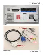
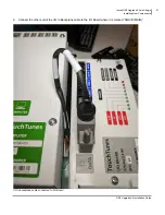
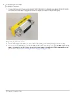
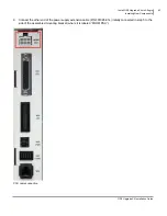
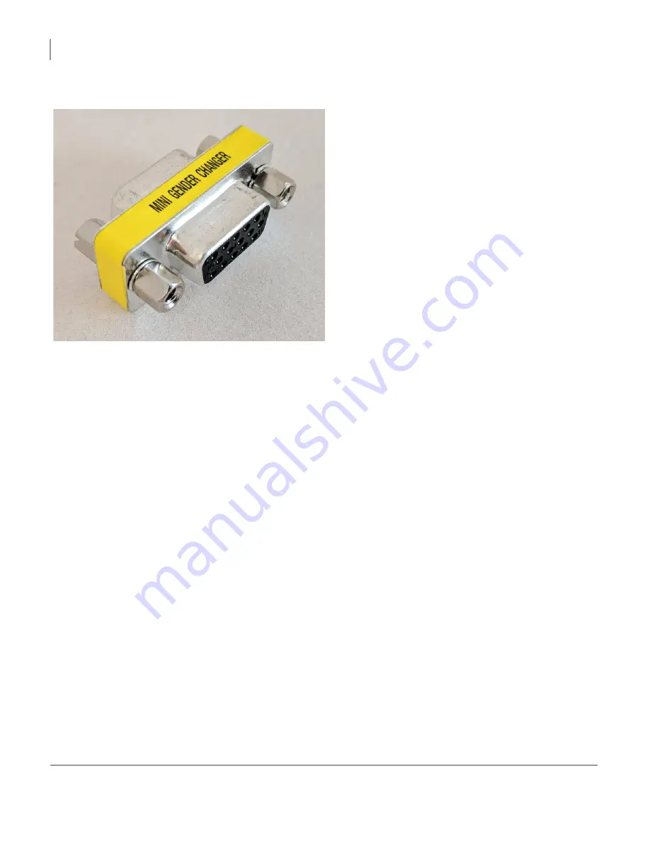
7. Connect the blue end of the new video cable (P/N 301096-036) to the Male/Female adapter (P/N 401704-001). 

The white end of this cable is plugged into the new computer (as shown in the previous figure).

Mini gender adapter for video cables

8. Connect the adapted end of the new video cable to the existing video cable (which goes to the monitor).
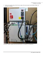
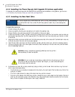
9. Connect one end of the AC power cord to the PSU and the other end to the power supply (

for MJS replacement 

only

). This cable (P/N 301097-036) is found in the Power Supply Unit Upgrade Kit (which is assembled in the 

procedure in section 

4.2.3  Assembling the Power Supply Unit Upgrade Kit

).

Summary of Contents for TouchTunes Allegro

Page 1: ...OS2 Upgrade Kit Installation Guide MX 1 Allegro...

Page 2: ......

Page 3: ...ges may be periodically made to the information set forth in this Guide which changes will be incorporated into new editions of this Guide TouchTunes will not be held liable for any damages resulting...

Page 4: ...d other works of authorship You may not infringe or otherwise violate the rights secured by the Intellectual Property Moreover you agree that you will not and will not attempt to modify prepare deriva...

Page 5: ...uter and I O Board Upgrade Kit Components 8 2 4 2 Power Supply Unit Upgrade Kit Components 9 2 5 Workflow 9 3 Install OS2 Upgrade Kit in MX 1 11 3 1 Removing JCB or JCB for JCB Computer 12 3 2 Install...

Page 6: ...uring the Jukebox 66 5 2 1 Calibrating the Touchscreen 66 5 2 2 Selecting Configuration Settings 66 5 2 3 Selecting Languages 67 5 2 4 Choosing Jukebox Settings 67 5 2 5 Choosing Calling Window and Co...

Page 7: ...duction This section introduces the OS2 Upgrade Kits for TouchTunes jukeboxes provides important safety information and describes how to get technical support Topics 1 1 About This Guide 1 2 Disclaime...

Page 8: ...attachments or peripherals improper use environment installation or electrical supply improper maintenance any other misuse abuse or mishandling 1 2 2 Important Safety Instructions Make sure to famili...

Page 9: ...e manufacturer s instructions To ensure reliable operation of the product and to protect it from overheating put the product in a position and location that will not interfere with its proper ventilat...

Page 10: ...53 To help us assist you more effectively with problem reports the following information may be required when contacting TouchTunes Technical Support Jukebox model and ID Operator ID The serial number...

Page 11: ...an OS2 Upgrade Kit Topics 2 1 Important Prerequisites 2 1 1 Jukebox Condition 2 1 2 Broadband Internet Connection 2 1 3 Record Current Jukebox Settings 2 2 Required Tools and Equipment 2 3 Estimated T...

Page 12: ...ions ensure you use high quality cable and make the cable run as short as possible to minimize potential problems due to line noise and interference Wireless Broadband Connection The TouchTunes Wirele...

Page 13: ...minutes 2 4 Unpacking and Checking OS2 Upgrade Kit Components The TouchTunes Universal Computer and I O Board Upgrade Kit P N 600305 001 for jukeboxes may be delivered in several boxes and includes t...

Page 14: ...ket support parts 401690 001 1 MET SUPPORT MIDDLE BRACKET Middle part for metal riser bracket 401691 001 2 MET SUPPORT STAND BRACKET Side support parts for metal riser bracket 401692 001 1 ASY PC IO B...

Page 15: ...This procedure involves assembly installation and connection of the new TouchTunes components in the jukebox 3 Activation of the upgraded jukebox This procedure allows you to verify the success of you...

Page 16: ...OS2 Upgrade Kit Installation Guide Prepare to Install OS2 Upgrade Kits Workflow 10...

Page 17: ...e performed in order to complete the installation of the OS2 Upgrade Kit in an MX 1 jukebox Topics 3 1 Removing JCB or JCB for JCB Computer 3 2 Installing New Components 3 2 1 Assembling the Universal...

Page 18: ...plies to a jukebox equipped with a JCB or JCB for JCB computer To remove the computer 1 Power off the jukebox 2 Disconnect all electrical power to the jukebox 3 Unlock and open the jukebox front door...

Page 19: ...ade Kit Installation Guide 13 Unlocking MX 1 Service Tray Disengage the rails from the locking tabs by pressing them inward toward the center of the enclosure and then pulling back as far as they can...

Page 20: ...f the JCB MX 1 jukebox accessed from its rear service tray NOTE Prior to performing the next step it is recommended to use cable flags or just pieces of tape to tag each cable that connects to the juk...

Page 21: ...Kit Installation Guide 15 Connections to remove from bottom of the JCB MX 1 jukebox accessed from interior of jukebox 7 Find the four screws that hold the computer in place and remove each one hold th...

Page 22: ...OS2 Upgrade Kit Installation Guide Install OS2 Upgrade Kit in MX 1 Removing JCB or JCB for JCB Computer 16 Remove the screws from the JCB 8 Pull out the computer and set it aside...

Page 23: ...ide 17 3 2 Installing New Components 3 2 1 Assembling the Universal Computer and I O Board Upgrade Kit 1 Unpack the Upgrade Kit components Metal riser bracket pieces NOTE The two optional pieces can b...

Page 24: ...OS2 Upgrade Kit Installation Guide Install OS2 Upgrade Kit in MX 1 Installing New Components 18 Mounting bracket for Computer and I O Board...

Page 25: ...allation Guide 19 Computer IMPORTANT NOTE The new computer P N 301090 001 is marked with a green label to indicate it is universal If the P N and label of the computer you receive does not match with...

Page 26: ...ade Kit Installation Guide Install OS2 Upgrade Kit in MX 1 Installing New Components 20 I O Board Upgrade Kit cables RJ cables not shown I O to backplane Video cable Power extension Male Female video...

Page 27: ...Install OS2 Upgrade Kit in MX 1 Installing New Components OS2 Upgrade Kit Installation Guide 21 2 Place the riser bracket pieces as follows Position metal riser bracket pieces...

Page 28: ...in your OS2 Upgrade Kit two on either side to attach the center piece to both side pieces Use the screws with P N 200244 006 Assembled metal riser bracket The assembled metal riser bracket will be in...

Page 29: ...Install OS2 Upgrade Kit in MX 1 Installing New Components OS2 Upgrade Kit Installation Guide 23 4 Locate the I O to Backplane cable I O to Backplane cable...

Page 30: ...MX 1 Installing New Components 24 5 Connect the end labeled Backplane to the backplane PCB it should click into place Connecting cable to backplane 6 Place the computer onto the mounting bracket by l...

Page 31: ...y fastening it with four screws provided in your OS2 Upgrade Kit Use the screws with P N 200244 006 Location of screws to secure the computer to the mounting bracket 8 Place the I O Board onto the mou...

Page 32: ...nstallation Guide Install OS2 Upgrade Kit in MX 1 Installing New Components 26 9 Connect the other end of the I O to Backplane cable to the I O Board where it is marked SQUID MAIN I O Main cable conne...

Page 33: ...sal Computer and I O Board Upgrade Kit To install the Computer and I O Board assembly 1 Install the metal riser bracket by fastening four screws found in your OS2 Upgrade Kit on top of the existing mo...

Page 34: ...nstallation Guide Install OS2 Upgrade Kit in MX 1 Installing New Components 28 2 Connect the following extension cable to the MX 1 power supply cable highlighted in the previous figure Extension cable...

Page 35: ...e Kit Installation Guide 29 3 Align the flange hooks on the assembled mounting bracket with the two rectangular holes on the metal riser bracket and then rest the assembled mounting bracket on the ris...

Page 36: ...Upgrade Kit in MX 1 Installing New Components 30 4 Fasten two screws to the top right and left of the assembled mounting bracket to secure it to the metal riser bracket Use the screws with P N 200244...

Page 37: ...the old computer to the Computer and I O Board as follows All connections are labeled Connections on MX 1 installation for JCB replacements 6 Connect the blue end of the new video cable P N 301096 036...

Page 38: ...e The hard drive and its enclosure are shipped separately from the OS2 Upgrade Kit If the hard drive has not yet arrived at your location contact TouchTunes 5 Align the hard drive enclosure with its s...

Page 39: ...the spring is not visible There is no gap between the edge of the hard drive tray and the computer There is no play between the hard drive and the computer when you pull outward on the handle of the...

Page 40: ...OS2 Upgrade Kit Installation Guide Install OS2 Upgrade Kit in MX 1 Installing New Components 34...

Page 41: ...jukebox Topics 4 1 Removing the Computer 4 1 1 Removing an MJS based Computer 4 1 2 Removing a JCB based Computer 4 2 Installing New Components 4 2 1 Assembling the Universal Computer and I O Board Up...

Page 42: ...shown 4 1 1 Removing an MJS based Computer This procedure applies to a jukebox equipped with an MJS computer or a JCB for MJS computer If your jukebox has a JCB or a JCB for JCB computer installed ski...

Page 43: ...all cabling connected to the MJS or JCB for MJS computer MJS computer connections in Allegro Installation NOTE Prior to performing the next step it is recommended to use cable flags or just pieces of...

Page 44: ...ter To remove the JCB computer 1 Power off the jukebox 2 Disconnect all electrical power to the jukebox 3 Unlock and open the jukebox front door 4 Disconnect the AC power cord from the power strip and...

Page 45: ...stallation Guide 39 5 Disconnect all cables from the computer Connections at top of JCB computer example shown without USB devices connected NOTE Connector locations are slightly different on a JCB fo...

Page 46: ...OS2 Upgrade Kit Installation Guide Install OS2 Upgrade Kits in Allegro Removing the Computer 40 Connections at bottom of JCB computer...

Page 47: ...ade Kit Installation Guide 41 6 Find the four screws that hold the computer in place and remove each one hold the computer in place while removing the last two screws to prevent it from falling Remove...

Page 48: ...Components 42 4 2 Installing New Components 4 2 1 Assembling the Universal Computer and I O Board Upgrade Kit 1 Unpack the components Metal riser bracket pieces NOTE The two optional pieces can be us...

Page 49: ...Install OS2 Upgrade Kits in Allegro Installing New Components OS2 Upgrade Kit Installation Guide 43 Mounting bracket for the computer and I O Board...

Page 50: ...g New Components 44 Computer IMPORTANT NOTE The new computer P N 301090 001 is marked with a green label to indicate it is universal If the P N and label of the computer you receive does not match wit...

Page 51: ...stall OS2 Upgrade Kits in Allegro Installing New Components OS2 Upgrade Kit Installation Guide 45 I O Board Replacement video cable I O to backplane Male Female video adapter Power extension Video cab...

Page 52: ...OS2 Upgrade Kit Installation Guide Install OS2 Upgrade Kits in Allegro Installing New Components 46 2 Place the riser bracket pieces as follows Position metal riser bracket pieces...

Page 53: ...nd in your OS2 Upgrade Kit two on either side to attach the center piece to both side pieces Use the screws with P N 200244 006 Assembled metal riser bracket The assembled metal riser bracket will be...

Page 54: ...OS2 Upgrade Kit Installation Guide Install OS2 Upgrade Kits in Allegro Installing New Components 48 4 Locate the I O to Backplane cable I O to Backplane cable...

Page 55: ...S2 Upgrade Kit Installation Guide 49 5 Connect the end labeled Backplane to the backplane PCB it should click into place Connecting cable to backplane 6 Place the computer onto the mounting bracket by...

Page 56: ...place by fastening it with four screws provided in your OS2 Upgrade Kit Use the screws with P N 200244 006 Location of screws to fasten computer to the mounting bracket 8 Place the I O Board onto the...

Page 57: ...s in Allegro Installing New Components OS2 Upgrade Kit Installation Guide 51 9 Connect the other end of the I O to Backplane cable to the I O Board where it is marked SQUID MAIN I O to backplane cable...

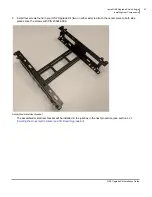
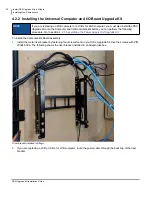
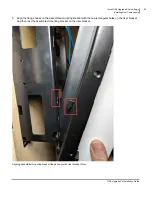
Page 58: ...rews with P N 200244 006 The following shows the riser bracket installed in an Allegro jukebox Riser bracket installed in Allegro 2 If you are replacing a JCB or JCB for JCB computer route the power c...

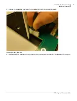
Page 59: ...it Installation Guide 53 3 Align the flange hooks on the assembled mounting bracket with the two rectangular holes on the riser bracket and then rest the assembled mounting bracket on the riser bracke...

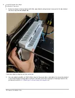
Page 60: ...the riser bracket Use the screws with P N 200244 008 Fasten assembled mounting bracket to the riser bracket 5 If you are replacing an MJS or JCB for MJS computer the power cable is extended by the ne...

Page 61: ...Upgrade Kit Installation Guide 55 6 Connect all connections removed from the old computer to the new computer and I O Board as follows All connections are labeled Connections on Allegro installation...

Page 62: ...uter as shown in the previous figure Mini gender adapter for video cables 8 Connect the adapted end of the new video cable to the existing video cable which goes to the monitor 9 Connect one end of th...

Page 63: ...de 57 4 2 3 Assembling the Power Supply Unit Upgrade Kit This procedure only applies when replacing an MJS computer or a JCB for MJS computer It is not applicable when replacing a JCB or JCB for JCB c...

Page 64: ...ents 58 2 Unpack the PSU Back of PSU 3 Place the PSU on the mounting bracket aligning the 4 metal studs with holes on the back of the PSU and ensuring the larger connector aligns with the correspondin...

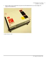
Page 65: ...Allegro Installing New Components OS2 Upgrade Kit Installation Guide 59 4 Attach the PSU to the mounting bracket using the screws P N 200244 006 from your Power Supply Unit Upgrade Kit P N 600304 001...

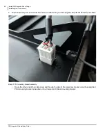
Page 66: ...mbly over and connect the extension cable from your OS2 Upgrade Kit P N 301095 014 as follows Back of PSU mounting bracket assembly Route the other end of this cable down and through the side of the m...

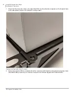
Page 67: ...de Kit Installation Guide 61 6 Align the flange hooks at the bottom of the assembled PSU mounting bracket with the slots located on the top of the assembled computer and I O Board mounting bracket Ali...

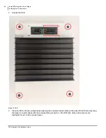
Page 68: ...U mounting bracket are aligned over the threaded holes on the assembled computer and I O Board mounting bracket Aligning mounting bracket holes for screws 8 Fasten the assembled PSU mounting bracket t...

Page 69: ...Components OS2 Upgrade Kit Installation Guide 63 9 Connect the other end of the power supply extension cable P N 301095 014 initially connected in step 5 to the side of the assembled mounting bracket...

Page 70: ...e in until it is completely seated 7 Using your fingers push in and then tighten the thumb screw clockwise on the hard drive tray until the thumb screw is securely tightened 8 Test whether the hard dr...

Page 71: ...he Jukebox 5 2 Configuring the Jukebox 5 2 1 Calibrating the Touchscreen 5 2 2 Selecting Configuration Settings 5 2 3 Selecting Languages 5 2 4 Choosing Jukebox Settings 5 2 5 Choosing Calling Window...

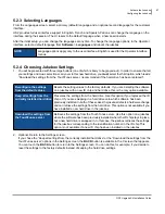
Page 72: ...uch the center of the target that appears on the lower left of the screen The Settings screen appears 5 2 2 Selecting Configuration Settings On the Settings screen you select the source for settings S...

Page 73: ...e in the C screen that appears You can touch the BACK button to return to the Settings screen You can do this for example if you decide to reset the settings to the factory defaults instead of keeping...

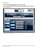
Page 74: ...ow and Connection Type After you choose the jukebox settings the Calling window and Connection type screen appears From here you select the nightly time range during which the jukebox communicates wit...

Page 75: ...IP address If you make a mistake use the Del key to erase the input and then re enter the correct information Use the Clear key to erase the entire contents of the IP address field Use the Cancel key...

Page 76: ...ugh the TouchTunes Tempo site are not registered on the jukebox until data access is restored 3 Check the information in the Activity messages After the jukebox is fully initialized the Attract screen...

Page 77: ...e Kit Installation Guide 71 5 3 Updating Software After you activate the jukebox TouchTunes recommends that you make sure that the jukebox has the most up to date software 1 Locate the Manager MNGR bu...

Page 78: ...Activate the Jukebox Updating Software 72 2 Press and release the MNGR button The Operator interface main menu appears Operator interface main menu 3 On the main menu press the DIAGNOSTIC button Diag...

Page 79: ...Hard Drive Corruption in the ID chip or hard drive can result in the jukebox being unable to play songs on the hard drive In this case the jukebox must download information from the TouchTunes server...

Page 80: ...o fit on 4 3 legacy screens Therefore viewing the OS2 interface on older screens causes a letterbox effect whereby black bars appear at the top and bottom of the screen as shown below This is expected...

Page 81: ......

Page 82: ......

Page 83: ...known as TouchTunes Interactive Networks Inc The Octave Music Group Inc 7250 Mile End Suite 202 Montreal Quebec Canada H2R 3A4 The Octave Music Group Inc 850 Third Ave 15th Floor New York NY 10022 USA...

Page 84: ...OS2 Upgrade Kit Installation Guide 901107 001 Rev 01...

Reviews:

Related manuals for TouchTunes Allegro