


14
Installation
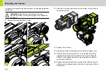
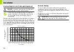
Payload Weight and C of G Height Adjustment
Maximum and minimum payloads that can be balanced are dependent
on the weight of the camera and accessories and on the centre of
gravity (C of G) height. The graph below shows the range of loads and
C of G heights that can be maintained in balance. The counterbalance
can be adjusted all the way to zero (no counterbalance) and the head
can still be tilted ±90º.
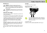
Numeric Display
The numeric display indicates the setting of the counterbalance
mechanism on a scale of 0-99%. Adjust the counterbalance crank
clockwise to increase the counterbalance setting and counter clockwise
to reduce it.
The display has a three color coded band offering advance warning of
cranking to the end limits.
WARNING!
For safe and reliable operation the head and all
mounted equipment must be correctly balanced.
If the correct numerical balance setting of the payload is
known, tilt the platform to the horizontal position and turn
the counterbalance crank until the display shows the
correct setting
2
4
6
8
10
12
14
16
0
10
20
30
40
50
60
70
80
90 100 110 120
5
9
14
18
23
27
32
36
41
45
50
54
51
102
152
203
254
305
356
406
Camera Centre of Gravity
Above Platform
2560 Counterbalance
Camera Weight
Kg
lbs
mm
in
CAUTION!
When cranking into the red zone be careful to
stop before reaching either 0 or 99% as damage could
occur.
Summary of Contents for 2560
Page 1: ...C1260 0002 2560 2560 Part No C1260 0001 www ocon com EN ...
Page 11: ...9 Installation ...
Page 25: ......
Page 26: ......
Page 27: ......
Page 28: ...www ocon com OConnor A Vitec Group brand Publication part No C1260 4980 1 ...


