background image


Document UT-MT-0046_EN 

Page 17 of 18 


Edition 04/06/2020 

Supersedes edition 11/03/2014 


ELEVATED RUNWAY EDGE LIGHT FAU 
INSTRUCTION MANUAL FOR USE, INSTALLATION AND MAINTENANCE 


4.5


REPLACEMENT OF THE CLEAR INNER LENS (ONE PIECE) 

Remove the three stainless steel clips, which locks the outer lens, by unscrewing the 
relevant screws; retain the hardware. Remove the outer lens and then the damaged 
inner  lens  complete  with  upper  block  and  gasket.  Mount  a  new  gasket  on  the  new 
inner  lens  in  fixed  position  and  then  the  above  assembly  on  the  lens  plate  in  fixed 
position;  place  the  upper  block  on  the  top  of  the  inner  lens  and  reassembly  by 
reversing  the  above  procedure.  The  arrows  on  the  top  of  the  inner  lens  must  be 
directed as the arrow of the outer lens. 

IMPORTANT:  IT  IS  SUGGESTED  TO  REPLACE  THE  INNER  LENS  GASKET  TO  NOT 
AFFECT


WATERTIGHTNESS. 


4.6


REPLACEMENT OF THE TWO COLOUR INNER LENS (TWO PIECES) 

Remove the three stainless steel clips, which locks the outer lens, by unscrewing the 
relevant screws; retain the hardware. Remove the outer lens and then the inner lens 
(in two pieces) complete with upper block and gasket.  Recover the eventual half-lens 
not damaged and the two silicone small spacers placed between the two half-lenses. 
Replace the damaged half-lens with a new one of the same colour and top mark. 

NOTE 
Each half-lens is top marked with the letter R (right beam) or the letter L (left beam) 
to provide the proper aiming of the beam in the horizontal plane as shown in Fig. 3.  


Between the two half-lenses place in low position the two silicone small spacers and 
in  up  position  the  silicone  securing  block.  To  fix  spacers  and  block  use  Loctite  601.  
Mount  a  new  gasket  on  the  above  assembly  in  fixed  position  and  then  the  above 
assembly  on  the  lens  plate  in  fixed  position;  reassembly  by  reversing  the  above 
procedure.  The  arrows  on  the  top  of  the  two  inner  half-lenses  must  be  directed  as 
the arrow of the outer lens 

IMPORTANT:  IT  IS  SUGGESTED  TO  REPLACE  THE  INNER  LENS  GASKET  TO  NOT 
AFFECT


WATERTIGHTNESS. 


4.7


REPLACEMENT OF THE COLUMN 

Open  the  light,  by  releasing  the  clamping  spring,  and  remove  the  grounding 
connection, by unscrewing the grounding bolt; retain the hardware.  
Cut the wire to remove the eyelet terminal.  
Remove the cable leads with plug from the clamping seat and disconnect the faston 
connections between the light cable leads and the lamp cable leads. 

Summary of Contents for FP150

Page 1: ...LIVERED BY MEANS OF THE AUTOMATIC KNOWLEDGE MANAGEMENT SYSTEM IT CAN BE SIGNED ON REQUEST THIS DOCUMENT AND THE DATA CONTAINED HERE IN IS PROPRIETARY PROPERTY AND SHALL NOT BE DUPLICATED USED OR DISCLOSED IN WHOLE OR IN PART FOR ANY PURPOSE WITHOUT WRITTEN CONSENT OF OCEM ELEVATED RUNWAY EDGE LIGHT FP150 INSTRUCTION MANUAL FOR USE INSTALLATION AND MAINTENANCE Compiled by Nicola Marabini Approved b...

Page 2: ...the applicable warranty period All costs of transportation of Products claimed not to be warranted and of those repaired or replaced to or from the facility of the Company shall be borne by Purchaser Company may require the return of any Product claimed not to be as warranted to its facility transportation prepaid by Purchaser to establish a claim under this warranty The cost of labour for the ins...

Page 3: ... the main circuit breaker and removed the supply to the unit by opening the circuit breaker switch on the distribution board at the beginning of the supply line Then wait discharge time at least 5 minutes ground carefully the system and check for voltage presence before accessing REANIMATION The maintenance staff must be aware of the risks related to electricity criteria to prevent the risk of ele...

Page 4: ...des edition 11 03 2014 ELEVATED RUNWAY EDGE LIGHT FAU INSTRUCTION MANUAL FOR USE INSTALLATION AND MAINTENANCE REVISIONS Index Date Description Edited by Approved by 01 04 06 2020 Update option M Bacciglieri M Mazzotti LIST OF EFFECTIVE PAGES From page 1 to page 18 ...

Page 5: ...Checks 13 4 1 2 Snowplow Operations 16 4 2 CLEANING OF THE OUTER LENS 16 4 3 RELAMPING 16 4 4 REPLACEMENT OF THE OUTER LENS 16 4 5 REPLACEMENT OF THE CLEAR INNER LENS ONE PIECE 17 4 6 REPLACEMENT OF THE TWO COLOUR INNER LENS TWO PIECES 17 4 7 REPLACEMENT OF THE COLUMN 17 4 8 REPLACEMENT OF THE CABLE LEAD 18 4 9 REPLACEMENT OF THE SUPPORT FOR LAMP 18 INDEX OF FIGURES Figure 1 Exploded View 7 Figure...

Page 6: ... outer Fresnel lens to optimize the horizontal candlepower distribution the inner surface of the lens is prismatic the outer is completely smooth for easy maintenance clear glass inner Fresnel lens when necessary the lens is supplied in two 180 pieces one or both coloured aluminium body with grounding bolt which mounts a suitable support for the lamp It is balanced on an aluminium column and fixed...

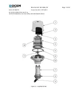
Page 7: ...Document UT MT 0046_EN Page 7 of 18 Edition 04 06 2020 Supersedes edition 11 03 2014 ELEVATED RUNWAY EDGE LIGHT FAU INSTRUCTION MANUAL FOR USE INSTALLATION AND MAINTENANCE Figure 1 Exploded View ...

Page 8: ...inner lens 1 5 Gasket for inner lens 1 6 Gasket for outer lens 1 7 Breakable coupling 1 8 Ring nut 1 9 FAA L 823 plug 1 10 180 left inner lens 1 11 Lamp 1 12 Lamp support 1 Figure 2 Part List spun aluminium screen suitable to be mounted between the inner lens and the outer lens to provide a 180 beam available on request spun aluminium daymarker cone available on request All hardware is made of sta...

Page 9: ...N Compliance I ICAO 60m Runway Edge S ICAO 45 m Runway Edge and Instrument Threshold End F FAA Runway Edge Colour Side L Colour Side R C White G Green Y Yellow R Red X Screened Lamp Type 150 150W 6 6A PK 30 d Options C Daymarker Cone The beams aiming is not field adjustable F P 1 5 0 THRESHOLD CENTERLINE Threshold SIDE Runway End SIDE Threshold SIDE Runway End SIDE L R R L L R R L CENTRELINE C C Y...

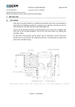
Page 10: ...ting transformer is housed into a separate concrete pit which is normally placed close the above concrete block Figure 4 The pit can be placed far from the concrete block too but in this case a suitable cable duct has to be provided between the pit and the pipe elbow for passing the secondary cable As alternative the assembly pit pipe elbow can be replaced by a steel sheet base which can be used t...

Page 11: ...t is placed close to the top of the column lower threaded section screw the column to the pipe elbow during this operation leave the light open eventually supporting by hand the assembly lens plate lenses and take care to avoid the twisting of the grounding wire and the light cable leads after the screwing completion lock not tighten the column to the pipe elbow by means of the threaded ring nut t...

Page 12: ...CE 1 Lamp 7 Clamping seat for cable leads 2 Support for lamp with plug 3 Screws for lamp support fastening 8 Light levelling screws 4 Elastic mountings for lamp locking 9 Grounding bolt 5 Arrow marked on the lamp support 10 Hinge between lens plate 6 Cable leads with plug and body 11 Levelling and alignment device Figure 5 FP150 light Details 1 2 4 3 5 6 10 9 8 7 11 11 ...

Page 13: ...ng shall be limited to cleaning the prisms 4 1 MAINTENANCE PROGRAM In order to ensure maximum light fixture life the installed units should be subject to a maintenance program in accordance with the following instructions and taking as reference the Airport Service Manual ICAO Part 9 Airport Maintenance Practices or FAA AC 150 5340 30 4 1 1 Periodical Checks Daily Burnt out lamps Broken parts of l...

Page 14: ...er securing block for inner lens 5 Coloured half lens two pieces 2 Clear inner lens 6 Silicone small spacers between 3 Gasket for inner lens half lenses 4 Gasket for outer lens 7 Mark and arrow on the top of the half lenses 1 Reference on the body for outer lens proper mounting 2 Reference on the body for inner lens proper mounting Figure 6 FP150 light Details 1 2 3 4 5 7 6 9 8 ...

Page 15: ...ition 11 03 2014 ELEVATED RUNWAY EDGE LIGHT FAU INSTRUCTION MANUAL FOR USE INSTALLATION AND MAINTENANCE 1 References on the outer lens for proper mounting on the body 2 Reference s on the internal lens es to mount the gasket in fixed posiiton Figure 7 FP150 light Details ...

Page 16: ...plug from the clamping seat and disconnect the faston connections between the light cable leads and the lamp cable leads Remove the lamp by releasing the two elastic mountings Mount the new lamp in fixed position and reassembly by reversing the above procedure Take care the new lamp be identified by the same P N of the old one CAUTION TOUCHING THE QUARTZ BULB WITH YOUR BARE FINGERS MAY SERIOUSLY S...

Page 17: ...ete with upper block and gasket Recover the eventual half lens not damaged and the two silicone small spacers placed between the two half lenses Replace the damaged half lens with a new one of the same colour and top mark NOTE Each half lens is top marked with the letter R right beam or the letter L left beam to provide the proper aiming of the beam in the horizontal plane as shown in Fig 3 Betwee...

Page 18: ...etain the hardware Cut the wire to remove the eyelet terminal Remove the cable leads with plug from the clamping seat and disconnect the faston connections between the light cable leads and the lamp cable leads Unscrew the light and pull the cable leads with plug and the grounding wire through the bottom of the body and the column Disconnect the light plug from the secondary receptacle Pass the ne...

Reviews: