INSTALLATION
OPERATION
2
3
4
3
2.1 Unpacking the box
In the box you will find:
• 6010 Ethernet To HDMI Adaptor
• Micro HDMI to HDMI Cable
• This Manual
2.2 Choosing a mounting location
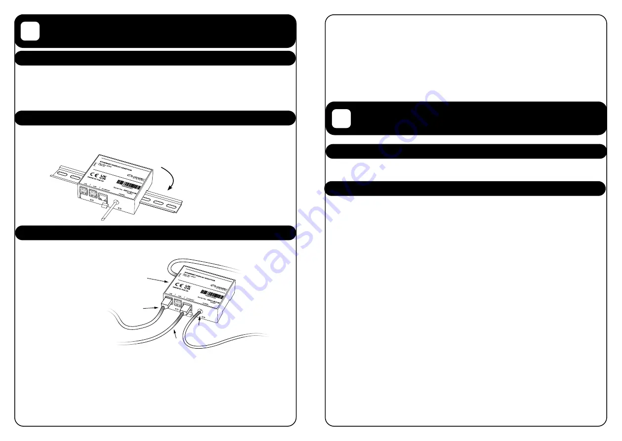
The 6010 is designed for use with a DIN rail and should be mounted in a dry, cool location a
maximum of 10 metres from the display that it is intended to drive. The unit should not be
exposed to direct sunlight.
2.3 Connecting the 6010 Ethernet To HDMI Adaptor
The 6010 Ethernet to HDMI has 4 connections that need to be made in order to use the unit:
2.3.1 Ethernet
Connection
The unit should be
connected via CAT5
Ethernet cable to the
same network as the
Poseidon System unit.
2.3.2 HDMI
Connection
The unit should be
connected to the display
using the included Micro
HDMI to HDMI Cable. The micro HDMI cable should connect to the 6010 at the port marked
HDMI on the front label. The full-size HDMI cable should connect to the display to be driven.
2.3.3 USB Connection
Any USB port on the 6010 can be used to connect the 6010 to the USB connection on the
Display. Please refer to your display documentation for information on how to connect it to
a USB cable.
3.1 Turning the unit on / off
When the power supply to the 6010 is available, the 6010 will automatically turn on. You do
not need to shut the unit down manually before switching the power off.
3.2 First use
Please ensure that your router has broadcast enabled and that the Poseidon System has
a static IP before proceeding.
When turning the 6010 on, you will see a message that the unit is searching for the Poseidon
system. This process is automatic.
After the Poseidon system has been found, you will be prompted to enter a PIN number.
This is the Administrator PIN of the Poseidon System and defaults to 1111.
• Enter the pin, and press accept. You will now be asked to name the device and select
the screen to connect
•
Name the device according to the device location, for example, “Aft Display”
•
Select the page set to display, for new / unconfigured systems this will
default to “MAIN”
•
Press accept
If your router does not support broadcast, the auto-configuration will not work and there is
an alternate method to configure the 6010.
To manually configure the 6010, create a text document named “IP” (Note, no .txt
extension).
In this file enter the IP address of the Poseidon System, for example:
192.168.16.200
Then, save this file to a USB memory stick on the root folder (ie. E:/) and insert it into the
6010. The 6010 will now load the Poseidon System Page and you can remove the USB from
the 6010.
2.3.4 Power Connection
The 6010 includes a 1-metre tail for connecting the unit to a 9-32V DC power supply. It is
recommended that this power supply is ground referenced the same as the display that it is
to be connected to. It is recommended to connect the 6010 to a switchable power supply as
the 6010 does not have on/off power control. The 6010 has an internal resettable fuse, so an
external fuse is not required.
Once all connections are made, please ensure to securely retain all cables appropriately so
that they do not work loose under vibration.
Unit clips
onto a Din Rail
Ethernet cable
USB port for
touchscreen
Micro HDMI
Power Connection


