background image

5 | EN

PYROPLUG

®

 MagicBox

About these instructions

1  About these instructions

1 1 

Target group

These instructions are aimed at specialists trained in fire protection. 

1 2 

Relevance of these instructions

These instructions are based on the standards valid at the time of compi-

lation (August 2022).

Please read the instructions carefully before starting mounting. We will 

not accept any warranty claims for damage caused through non-obser-

vance of these instructions.

Any images are intended merely as examples. Mounting results may look 

different.

In these instructions, cables and lines are referred to simply as cables.

To find out more about planning and mounting the product, we recom-

mend a comprehensive training course.

1 3 

Types of warning information

Type of risk!


Shows a risky situation. If the safety instruction is not observed, then 

medium or minor injuries may occur.

Note!


Indicates important information or assistance.

1 4 

Basic standards and regulations


– EN 1366 Part 3


– EN 13501 Parts 1 and 2


– EN 1363


– EU BauPVO (CPR)

1 5 

Applicable documents


– European Technical Assessment ETA-22/0175


– Safety data sheet, PYROSIT

®

 NG fire protection foam


– Declaration of performance 05-DOP-014


– General construction type approval Z-19.53-2618

2  Intended use

PYROPLUG

®

 MagicBox is an insulation system for the interior of build-

ings.


It closes openings in fire-resistant walls with component thicknesses 

of 100 mm or more or ceilings of 150 mm or more, through which the ca-

VORSICHT

Summary of Contents for PYROPLUG MagicBox

Page 1: ...OBO Bettermann Holding GmbH Co KG Mounting instructions PYROPLUG MagicBox...

Page 2: ...2022 OBO Bettermann Holding GmbH Co KG The PYROPLUG system is a registered trademark of OBO Bettermann Holding GmbH Co KG PYROPLUG MagicBox Mounting instructions...

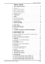
Page 3: ...x 4 sided 10 6 1 2 PYROPLUG MagicBox 3 sided 11 6 2 Component thicknesses component spacings and insulation spacings 11 6 3 Approved assignment 12 6 4 Minimum distances between installations 13 7 Moun...

Page 4: ...4 EN OBO Bettermann Table of contents...

Page 5: ...about planning and mounting the product we recom mend a comprehensive training course 1 3 Types of warning information Type of risk Shows a risky situation If the safety instruction is not observed t...

Page 6: ...ble despite the opening without the application of fire insulation The installation of the fire insulation may not compromise the stabili ty of the adjacent elements even in the event of a fire Consul...

Page 7: ...ounting in walls and ceilings 3 sided variants for mounting in walls on the raw floor beneath sys tem floors and as insulation of rising sections in ceilings Available with the interior heights 60 mm...

Page 8: ...Box Inlay blocks PMB SI 4 PMB SI 8 item no 7204184 7204188 Closure of larger cavities or reserve insulation KS S DE identifica tion plate item no 7205425 Labelling of the insulation PMB GS graphite st...

Page 9: ...the first support of pass through installations in fire insulation Mounting of the bracket on the wall support of the installation using mounting rail Available up to a width of max 400 mm Tab 1 Acces...

Page 10: ...ion spacings Abb 5 1 2 3 4 5 Insulation distances to other components or component openings Item Designation Wall mm Ceiling mm 1 Component thickness 100 150 2 Insulation thickness corresponds to the...

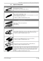
Page 11: ...Mesh cable trays Other assignment Klimasplit cable combinations consisting of copper pipes up to 22 22 mm with heat insulation condensate hose and up to three accompanying cables For details see aBG...

Page 12: ...installations 20 mm Distance between hydraulic lines and other installations 50 mm Distance between all other installations 0 mm 7 Installation 7 1 Mounting the 4 sided PYROPLUG MagicBox 7 1 1 Wall mo...

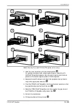
Page 13: ...ween the component opening and last sus pension of the cable support system and click together 2 Measure the wall thickness and attach the graphite strips symmetri cally at the appropriate distance 2...

Page 14: ...unting in a group arrangement the mounting of the individual PYROPLUG MagicBoxes takes place as described in 7 2 1 Wandmontage auf Seite The cavities between the PYROPLUG MagicBoxes do not have to be...

Page 15: ...together 1 2 Measure the wall thickness and attach the graphite strips at the appropriate distance 2 Attach the first graphite strip flush to the edge of the PYROPLUG MagicBox Attach the second graph...

Page 16: ...iller 4 6 Perform the installations 7 Fill larger cavities with inlay blocks 5 8 Close off the residual opening with PYROSIT NG fire protection foam 6 Create equipotential bonding using flat connector...

Page 17: ...ided PYROPLUG MagicBox wall mounting 1 Measure the wall thickness and attach the graphite strips symmetri cally at the appropriate distance 1 2 Insert the PYROPLUG MagicBox into the component opening...

Page 18: ...lausgleich anschlie en auf Seite Attach the identification plate see 7 4 Kennzeichnungsschild anbring en auf Seite Group arrangement In the case of mounting in a group arrangement the mounting of the...

Page 19: ...MagicBox ceiling mounting 1 Measure the wall thickness and attach the graphite strips at the ap propriate distance 1 Attach the first graphite strip flush to the edge of the PYROPLUG MagicBox Attach t...

Page 20: ...penings with PYROSIT NG fire protection foam 6 Create equipotential bonding using flat connectors see 7 3 Potentia lausgleich anschlie en auf Seite Attach the identification plate see 7 4 Kennzeichnun...

Page 21: ...ng individual cables Penetrate the foam with an installation pipe Then close off residual openings with PYROSIT NG fire protection foam 8 Maintaining the system The PYROPLUG MagicBox insulation system...

Page 22: ...300 x 123 x 130 mm PMB 620 4 A2 7204004 300 x 223 x 130 mm PMB 630 4 A2 7204008 300 x 323 x 130 mm PMB 640 4 A2 7204012 300 x 423 x 130 mm PMB 650 4 A2 7204016 300 x 523 x 130 mm PMB 660 4 A2 7204020...

Page 23: ...eight 110 mm 10 4 3 sided PYROPLUG MagicBox interior height 110 mm Type Item no Dimension PMB 110 3 A2 7204150 300 x 123 x 166 mm PMB 120 3 A2 7204154 300 x 223 x 166 mm PMB 130 3 A2 7204158 300 x 323...

Page 24: ...OBO Bettermann Holding GmbH Co KG P O Box 1120 58694 Menden GERMANY Customer Service Germany Tel 49 0 2373 89 1700 Fax 49 0 2373 89 1238 E mail info obo de www obo bettermann com OBORD 210775 10 2022...

Reviews: