background image

9

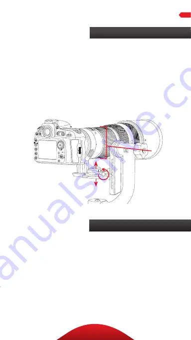
Vertical Balance

1. Loosen the platform adjustment knob, and adjust the height 

to vertically align the center of the lens with the axis of the 

tension control knob. Re-tighten the platform adjustment 

knob after every adjustment.

2. After each adjustment, test the balance by pointing the 

lens up and down. If the lens and camera can be tilted at 

any angle and remain in place, they are now vertically and 

horizontally balanced.

Balancing a Lens

OPERATION

Pro Tips

•  For each setup, use masking tape or a grease pencil to 

note the position on the swinging arm and along the 
QR plate. This will make balancing the camera and 
lens much faster in the future.

•  To maximize image sharpness, support the camera 

with your right hand while resting your left hand on 
the front third of the lens.

Summary of Contents for GH-30

Page 1: ...1 GH 30 30C Gimbal Head You reonsteadyground Model GH 30 shown ...

Page 2: ...a positioning to capture the desired subject even with a heavy lens Lenses that are large or heavy enough to affect quick moving and aiming can be tilted or swiveled effortlessly and remain securely in place once positioned Engineered with a strong and durable curved main arm both heads support up to 44 pounds yet balances the load so even a large lens feels weightless An arca type quick release p...

Page 3: ..._____________________________ 7 BalancingaLens____________________________________________________________________________________ 8 9 ProTips________________________________________________________________________________________________________________ 9 Specifications____________________________________________________________________________________________ 10 Warnings_________________________...

Page 4: ...4 KEY FEATURES ...

Page 5: ...ingingarmscalemarks Curvedmainarm Platformadjustmentknob Plateplatform 1 4in mountingscrews 2 Arca typequick release QR plate Platereleaselock Panninglock Panningbase 3 8in tripodmountingsocket Panningdegreemarks 1 4to3 8in bushing 2 A G M B H N D I C E J F L K ...

Page 6: ...m to secure the gimbal to the tripod Important Make sure the head is screwed on securely so there are no gaps between the base and the tripod 1 Loosen the platform adjustment knob and slide the platform down to the bottom of the arm 2 Tighten the platform adjustment knob until the plate platform is securely locked MounttheGimbaltotheTripod AttachthePlatePlatformtotheGimbal OPERATION ...

Page 7: ... the screws of the quick release plate with the D rings and then tighten them with a coin or slotted screwdriver AttachtheQRPlatetotheLens MountingaLens OPERATION 1 Tighten the swinging arm lock panning lock and platform adjustment knob and make sure they are secure 2 Loosen the plate release lock and place the QR plate and lens assembly into the plate platform s grooves 3 Make sure the QR plate i...

Page 8: ... lens on the gimbal head Horizontal Balance 1 Tighten all locking knobs so the camera and lens won t accidentally move when mounted on the gimbal 2 Loosen the plate release lock and adjust the horizontal balance of the camera and lens Tighten the plate release lock until secure before proceeding 3 Loosen the swinging arm lock and tilt the lens up and then down at a 45 angle If the lens wants to re...

Page 9: ... lens up and down If the lens and camera can be tilted at any angle and remain in place they are now vertically and horizontally balanced BalancingaLens OPERATION ProTips For each setup use masking tape or a grease pencil to note the position on the swinging arm and along the QR plate This will make balancing the camera and lens much faster in the future To maximize image sharpness support the cam...

Page 10: ... Do not exceed the head s maximum load capacity of 44 pounds 20 kg Ensure that all appropriate locks are engaged when necessary Keep out of reach of children All images are for illustrative purposes only SPECIFICATIONS WARNINGS GH 30 GH 30C BaseDiameter 2in 5 1cm 2 4in 6cm BasePanRange 360 360 Width 9 3in 23 6cm 9 3in 23 6cm Height 9in 22 9cm 9 1in 23 1cm Weight 3 15lb 1 4kg 2 7lb 1 22kg MaximumLo...

Page 11: ... damage or defect caused by misuse neglect accident alteration abuse improper installation or maintenance EXCEPT AS PROVIDED HEREIN THE WARRANTY PROVIDER MAKES NEITHER ANY EXPRESS WARRANTIES NOR ANY IMPLIED WARRANTIES INCLUDING BUT NOT LIMITED TO ANY IMPLIED WARRANTY OF MERCHANTABILITY OR FITNESS FOR A PARTICULAR PURPOSE This warranty provides you with specific legal rights and you may also have a...

Page 12: ...12 www obensupports com GG2 ...

Reviews: