background image

Centre tapped wallwarts and linelumps

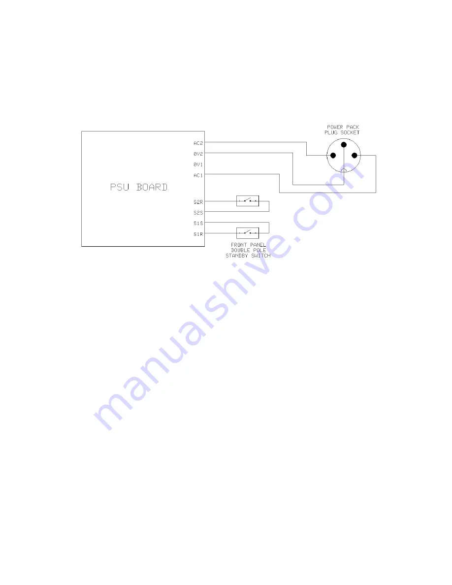
Centre tapped linelumps like the Yamaha PA-20 will have three wires coming from their 
connector. It will have two AC outputs and one 0V. Take one of the AC outputs to terminal 
AC1 and the other AC output to terminal AC2. It should not matter which AC output goes to 
AC1 or AC2. The 0V should go to the 0V2 terminal. The 0V1 terminal is left unused.

Figure 2. Linelump wiring with centre tapped output, eg. Yamaha PA-20

The front panel switch is a double pole single throw (DPST) switch which connects S2R and 
S2S together, and S1R and S1S together, when switched on. You can replace the switch with 
two wire links, but I do recommend that a switch be fitted so the socket doesn't have to take 
the full surge current when you insert it if the linelump is powered up.

I also recommend fitting the AC indicator LED too. This is so you know the linelump is on. 
The AC indicator is designed to indicate the status of incoming power and is not determined 
by the position of the standby switch.

The standby switch should not be used to turn the unit off permanently. This should be done 
by either switching the adapter off at the mains socket, or by pulling the adapter's plug out of 
the mains socket.

R5 should be fitted and is a 47R, 1/4W resistor.

9

Summary of Contents for Rack Power Supply Unit (RPSU)

Page 1: ...Oakley Sound Systems Rack Power Supply Unit RPSU PCB Issue 1 User Manual V1 0 1 Tony Allgood Oakley Sound Systems CARLISLE United Kingdom 1...

Page 2: ...rmation about suitable sources for your low voltage AC power supply The Oakley PSU allows for various options in the installation You can use the unit either in full wave rectification mode for connec...

Page 3: ...ection to the mains or other high voltage sources further to what is provided in this document Please do not ask us for additional information pertaining to direct mains connections or using internall...

Page 4: ...e connecting to the power supply One HVM will draw around 80mA from the 15V supply and 80mA from the 15V supply The Oakley RPSU features current limiting but only what is built into the two power devi...

Page 5: ...ave rectification The fuse type should be a slow blow or anti surge type The size is 20mm It should be rated at between one and two times the maximum current of your wallwart Thus a 500mA AC output ma...

Page 6: ...e output voltage You should select 15V for operation with the RPSU board I do not recommend you take more than 125mA per rail Because this is a single phase unit the Oakley PSU is wired in half wave r...

Page 7: ...ropriate socket If you wish you can ditch their connector and use your own Maplin in the UK sell a suitable three way connector to fit the Yamaha one perfectly Their part number is FM51F In the UK the...

Page 8: ...ly connects S1R and S1S together when switched on You can replace the switch with a simple wire link but I do recommend that a switch be fitted so the socket doesn t have to take the full surge curren...

Page 9: ...R and S2S together and S1R and S1S together when switched on You can replace the switch with two wire links but I do recommend that a switch be fitted so the socket doesn t have to take the full surge...

Page 10: ...r information other than that included here will be provided by myself or Paul Darlow regarding the construction of mains powered items For powering a HVM and an SE330 together then the mains transfor...

Page 11: ...ble insulated case is not practical you should ensure that any exposed external metal parts be properly earthed The case should be bonded to earth using an M4 screw toothed washer washer solder tag an...

Page 12: ...Mains wiring diagram For experienced builders only 12...

Page 13: ...and I are on this group as well as many other users and builders of Oakley modules If you have a comment about this user manual or have a found a mistake in it then please do let me know Last but not...

Reviews: