


TWR-56F8400 User’s Manual
Page 5 of 35
o
Voltage translators between 5V MC9S08JM60 MCU chip and 3.3V MC56F84789 DSC
chip
1.1
Block Diagram
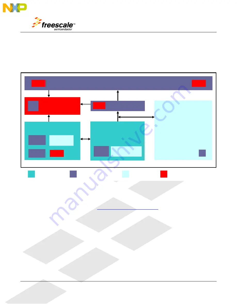
A block diagram for the TWR-56F8400 is shown in Figure 1 below.
Figure 1.
TWR-56F8400 Block Diagram
1.2
Reference Documents
The documents listed below should be referenced for more information on the Freescale Tower
system and the TWR-56F8400. Refer to
http://www.freesale.com/tower
for the latest revision of all
Tower documentation.
•
Freescale Tower Electromechanical Specification
•
TWR-56F8400 Quick Start Guide
•
TWR-56F8400 Lab Tutorials
•
MC56F84XXX Reference Manual
•
MC56F84XXX Data Sheet
•
MC56F84XXX Chip Errata [if exists]
•
AN3561, USB Bootloader for the MC9S08JM60
•
Serial Bootloader for MC56F84XXX User Guide
•
APMOTOR56F8000e Motor Control Demonstration System User Manual
Motor Control&
Aux Connectors
Tower Elevator Expansion Connectors
(SPI, I2C, ADC, FEC, TPM, SCI, KB, etc.)
5.0V
3.3V
Freescale Device
External Connectors
Interface Circuits
Power
OSBDM (MC9S08JM60 MCU
Debug, Power, SCI Headers)
5.0V
USB
Mini-AB
Voltage
Translators
BDM
Header
•
LEDs & Buffers (9)
•
IRQ PB & HDRs (2)
•
RESET PB
•
Thermistors & HDRs (4)
•
Analog Filters
•
Microphone (optional)
•
CAN XCVR & HDR
Barrel Power Connector
Power Selection HDRs
Voltage Regulator
5V-
9V
3.3V
MC56F84789
Digital Signal Controller
JTAG
Header
Boot load HDR


