NXP Semiconductors Symphony SoundBite Reference Manual Download Page 2

Symphony SoundBite Reference Manual, Rev. 2.0

2

Freescale Semiconductor


Introduction

1

Introduction

The Symphony SoundBite is a versatile audio application development board built upon the DSPB56371 
Digital Signal Processor. The Symphony SoundBite costs very little and is ideal for cost-sensitive 
organizations, like university digital signal processing labs, small engineering companies, and even the 
frugal hobbyist. 

Capable of simultaneously processing 8 
independent or 4 stereo pairs of audio 
input and output, the Symphony 
SoundBite has 4 stereo input and output 
jacks to connect to line-level analog 
audio. One pair of input and output jacks 
is shared with an optical S/PDIF receiver 
and transmitter, enabling direct digital 
audio input and output (mini TOS-link). 
Four 24-bit stereo codecs handle analog 
conversion at sampling rates up to 192 
kHz. You can also interact with 
application code running on the DSP, 
using DIP switches and multi-colored 
LEDs (connected to GPIO pins).

The board includes an integral, 
multi-mode communication and 
debugging interface that enables low 
level JTAG debugging, in addition to 
high-level serial communications with the DSP via SPI or I

2

C.

Features:

Main Processor: 24-bit DSPB56371 Digital Signal Processor

— up to 180 million instructions per second (MIPS) at 180 MHz core clock

— 1.25 V core supply with 3.3 V peripheral I/O supply

— Dual-Harvard architecture core (two data memory spaces in addition to program space)

— On-chip memories:

– 4–44K x 24-bit words of PRAM

– 28–36K x 24-bit words of XRAM

– 16–48K x 24-bit words of YRAM

– User-configurable memory partitions

— Two Enhanced Serial Audio Interfaces (ESAIs) provide up to 8 channels of digital audio input 

and output

— Serial Host Interface (SHI) provides interface for high level serial communication

— Triple timer module

— Serial I

2

C boot EEPROM allows for fully stand-alone operation of Symphony SoundBite

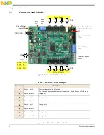
Figure 1. Symphony SoundBite Audio Demo Board

Summary of Contents for Symphony SoundBite

Page 1: ...Document Number SNDBITERM Rev 2 0 09 2008 Symphony SoundBite Reference Manual Contents Section 1 Introduction page 2 Section 2 Functional Blocks page 3 Section 3 Configuration and Connections page 5...

Page 2: ...interact with application code running on the DSP using DIP switches and multi colored LEDs connected to GPIO pins The board includes an integral multi mode communication and debugging interface that...

Page 3: ...ovides for low level JTAG OnCE and high level Symphony Debugger Interface debuggers Operational mode of integrated debugger hardware is controlled by host PC application software LEDs indicate the ope...

Page 4: ...is connected to a fixed gain preamplifier U14 which in turn is connected through jumper JP1 to the analog inputs at jack J1 The microphone gain can be adjusted further through the internal amplifier...

Page 5: ...evelopment board has powered up successfully Figure 3 shows a more detailed diagram of the off board and interconnections between the various functional blocks on the board Figure 3 Symphony SoundBite...

Page 6: ...ins MOD D A For the MOD pin switches positions 4 through 1 only the switch state is the inverse of the logic state presented to the pin so that in the ON position a logic low is presented to the corre...

Page 7: ...Input Output Jacks J1 J8 Jacks J1 J3 J5 and J7 accept line level analog inputs and jacks J2 J4 J6 and J8 provide line level outputs The analog and optical inputs and outputs of J1 and J2 are always e...

Page 8: ...3 6 General Purpose LEDs LED1 9 Nine LEDs are provided for general purpose use by DSP application code The GPIO pins connected to the LEDs should normally be configured as GPIO outputs A logic high ou...

Page 9: ...c low state which must be accounted for Although the GPLEDx lines are normally GPIO outputs the GPLEDx lines can be used as either inputs or outputs at the CON1 header NOTE When the GPLEDx lines are u...

Page 10: ...th channels of J1 through jumper JP1 J2 Stereo Output 0 J3 Stereo Input 1 Analog only J4 Stereo Output 1 J5 Stereo Input 2 Analog only J6 Stereo Output 2 J7 Stereo Input 3 Analog only J8 Stereo Output...

Page 11: ...ry switch resets the Symphony SoundBite board Jumper JP1 Microphone Select Route Microphone output to Left or Right Channel JP3 Power Source Select 3 pins 1 2 jumper Select external power supply 2 3 j...

Page 12: ...Additional Info 4 Additional Info For additional information please refer to the Symphony SoundBite Documentation Overview document which provides an overview of all the documentation relevant to the...

Reviews: