


UM10468
All information provided in this document is subject to legal disclaimers.
© NXP B.V. 2011. All rights reserved.
User manual
Rev. 1 — 30 August 2011
13 of 27
NXP Semiconductors
UM10468
SSL2108X buck evaluation board
Jumper J10A is connected in series with the brownout capacitor C8. Removing this
jumper sets the brownout protection trigger values to be reset to default value.
Remark:
Brownout protection is only available in the SSL21082 and SSL21084.
TVS Diode D2 is present to protect the DC circuit against overvoltage.
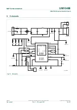
7. Board
optimization
The EMC filter calculations for components C1, C2, L1 are described in
AN11041
(see
). On the evaluation board, L2 and C8 have been added to provide extra filtering to
meet EMC norms.
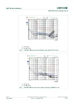
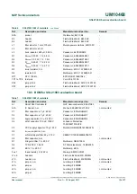
Power factor of the evaluation board depends mainly on the input resistance of the input
fused resistor FUS1. A higher resistance proportionally increases the power factor but
reduces the overall efficiency of the evaluation board.
Another way to get higher power factor is to add a valley fill circuit. The valley fill circuit
improves power factor with reduced efficiency losses. The disadvantage is the higher
component count needed.
gives an overview for the SSL21081 of input
resistance as a function of power factor and efficiency.
Remark:
Calculations for other components on the SSL2108X evaluation board can be
found in
AN11041
(see
(1) Efficiency curve.
(2) Power factor curve.
Fig 12. Input resistance (R
IN
) as a function of Power Factor (PF) and Efficiency (
)
019aac359
R
in
(Ω)
0
120
80
40
78
90
86
82
94
0.8
0.6
0.4
0.2
0.0
η
(%)
PF
(1)
(2)