


8
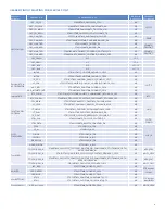
JUMPER SETTINGS (POWER SUPPLY)
JUMPER SETTINGS (LIN AND RTC CLOCK CONFIGURATION)
Jumper
Configuration
Description
J2
1-2 (Default)
The 3.3V supply powered from VBAT(+12V);
2-3
The 3.3V supply powered from P5V0(5V);
J8
1-2 (Default)
The P5V0 supply powered from SBC output ;
2-3
Not use, no power source(NC on J8-3);
J9
1-2 (Default)
The VDD supply powered from P3V3_SW(3.3V);
2-3
The VDD supply powered from P5V0(5V);
J29
1-2 (Default)
VCAN_SBC supply powered from P5V0_V1SBC;
2-3
VCAN_SBC supply powered from PVEXT_SBC;
J11
1-2 (Default)
It’s connected between VDD and VDD_MCU, and is designed for
S32K148 MCU low-power static current measurement, for this case,
R77 needs to be unmounted.
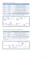
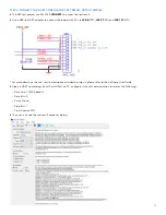
The jumper connection schematic is as below, details can be found in the board schematic;
Jumper
Configuration
Description
J32
short (Default)
Enable the LIN bus 1 pullup to work as a master node;
open
The LIN bus 1 is working as a slave node;
J33
short (Default)
Enable the LIN bus 2 pullup to work as a master node;
open
The LIN bus 2 is working as a slave node;
J34
1-2 (Default)
External active 32.768KHz oscillator for RTC is powered by VDD_MCU;
2-3
External active 32.768KHz oscillator for RTC is powered by VDD_MCU_
PERH;
External active 32.768 KHz oscillator for RTC schematic is as right, details can be found in the board
schematic and HW UG;