NXP Semiconductors S32K144 EVB Quick Start Manual Download Page 18

EXTERNAL USE

17

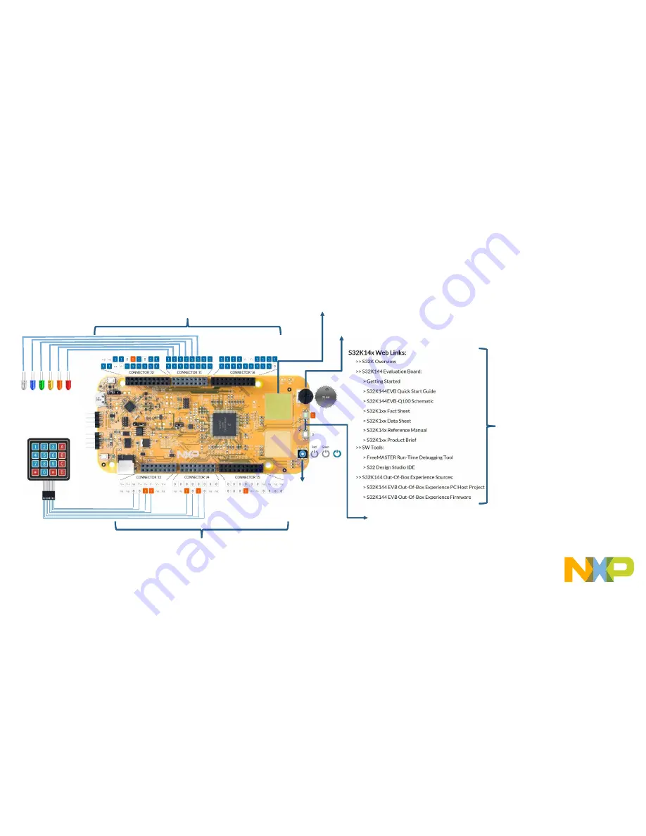
The FreeMASTER OOBE project description 

Links to S32K14x docs:

Fact Sheet

Data Sheet

Reference Manual

Product Brief

S32K144EVB schematic

S32K144EVB Quick Start 
Guide

Tools:

FreeMASTER

S32 Design Studio IDE

S32K144EVB OOBE source 
files

Pins of the J2, J1 and J6 connectors are configured as outputs. By 

single click on each pin you can change their logical level to log0 

or log1. User can connect e.g. LED diodes to these ouput pins. 

Pins of the J3, J4 and J5 connectors are configured as inputs. 

Logical level (log0/log1) is visualised for all connector pins. 

User can connect e.g. push-button keyboard to these input pins. 

RGB 

LED

Potentiometer

Touch Sense Electrodes

Mechanical 

Buttons

Summary of Contents for S32K144 EVB

Page 1: ...EXTERNAL USE REV4 2 APPLIES FOR S32K144 EVB SCH 29248 REV B QUICK START GUIDE S32K144 EVB...

Page 2: ...Get to Know S32K144 EVB Out of the Box Setup Out of the Box Experience OOBE based on the FreeMASTER tool Introduction to OpenSDA Creating a new S32DS project for S32K144 S32DS Debug basics Create a P...

Page 3: ...ion Bus RGB LED S32K144 MCU LIN Communication Bus OpenSDA USB Reset Button OpenSDA MCU OpenSDA JTAG Potentiometer User Buttons Get to know S32K144 EVB J2 Header J1 Header J6 Header J3 Header J4 Header...

Page 4: ...ebug adapter OpenSDA with support for several industry standard debug interfaces Easy access to the MCU I O header pins for prototyping On chip connectivity for CAN LIN UART SCI SBC UJA1169 and LIN ph...

Page 5: ...16 PTD7 GPIO J5 15 PTC2 ADC15 J5 18 PTD6 GPIO J5 17 NC GPIO J5 20 PTC15 GPIO J5 19 NC N A PIN PORT FUNCTION J1 PIN PORT FUNCTION J1 15 PTC11 PTE8 D7 J1 16 PTE3 GPIO J1 13 PTC10 PTC3 D6 J1 14 PTD3 GPI...

Page 6: ...Default Reset signal to OpenSDA use to enter into OpenSDA Bootloader mode Reset signal direct to the MCU use to reset S32K144 J107 1 2 2 3 Default S32K144 powered by 12V power source S32K144 powered b...

Page 7: ...M0 CH1 Potentiometer PTC14 ADC0_SE12 SW2 PTC12 SW3 PTC13 OpenSDA UART TX PTC7 LPUART1_TX OpenSDA UART RX PTC6 LPUART1_RX CAN TX PTE5 CAN0_TX CAN RX PTE4 CAN0_RX LIN TX PTD7 LPUART2_TX LIN RX PTD6 LPUA...

Page 8: ...EXTERNAL USE 7 S32K144 EVB OUT OF THE BOX...

Page 9: ...external 12V power supply By default USB power is enabled with J107 check slide 5 Connect the USB cable to a PC using supplied USB cable Connect other end of USB cable microUSB to mini B port on FRDM...

Page 10: ...ep 1 Power up the Board Is it powered on correctly When powered through USB LEDs D2 and D3 should light green Once the board is recognized it should appear as a mass storage device in your PC with the...

Page 11: ...EXTERNAL USE 10 Step 1 Power up the Board Is it powered on correctly Board is preloaded with a software in which the red blue and green leds will toggle at different rates...

Page 12: ...EXTERNAL USE 11 S32K144 EVB OUT OF THE BOX EXPERIENCE BASED ON THE FREEMASTER TOOL...

Page 13: ...EXTERNAL USE 12 Install the FreeMASTER tool Download and install the FreeMASTER PC application www nxp com FreeMASTER Open the FreeMASTER application on your PC You should see Welcome page...

Page 14: ...onnect the USB cable to a PC and connect micro USB connector of the USB cable to micro B port J7 on the S32K144EVB Allow the PC to automatically configure the USB drivers if needed When EVB is powered...

Page 15: ...Setup serial connection in the FreeMASTER tool Setup communication manualy Project Options Comm OR Setup communication automatically Tools Connection Wizard Setup communication port to opensda and spe...

Page 16: ...project will be automaticaly downloaded from www nxp com Once the FreeMASTER application detects the web address stored as an TSA active content in the flash memory of the S32K144 MCU the download of...

Page 17: ...EXTERNAL USE 16 The FreeMASTER OOBE project is loaded...

Page 18: ...les Pins of the J2 J1 and J6 connectors are configured as outputs By single click on each pin you can change their logical level to log0 or log1 User can connect e g LED diodes to these ouput pins Pin...

Page 19: ...oscope feature examples Display main project panel Project View Project Tree Display real time oscilloscope graph examples such as Potentiometer or Touch Sense Electrodes Analog values from potentiome...

Page 20: ...EXTERNAL USE 19 INTRODUCTION TO OPENSDA...

Page 21: ...et button SW5 4 Plug in a USB cable not included between a USB host and the OpenSDA USB connector labeled SDA 5 Release the Reset button A removable drive should now be visible in the host file system...

Page 22: ...f the srec files to the EVB S32K144 drive The new application should now be running on the S32K144 EVB Starting with v1 03 of the MSD Flash Programmer you can program repeatedly without the need to un...

Page 23: ...EXTERNAL USE 22 INSTALLING S32DS...

Page 24: ...EXTERNAL USE 23 Download S32DS Download S32DS from http www nxp com S32DS...

Page 25: ...EXTERNAL USE 24 CREATE A NEW PROJECT IN S32 DESIGN STUDIO...

Page 26: ...rst Time Select a Workspace Start program Click on S32 Design Studio for ARM v1 3 icon Select workspace Choose default see below example or specify new one Suggestion Uncheck the box Use this as the d...

Page 27: ...EXTERNAL USE 26 Create New Project Top Menu Selection File New Project...

Page 28: ...EXTERNAL USE 27 Create New Project S32DS Project Project Name Example FirstProject Project Type Select from inside executable or library folder Next...

Page 29: ...EXTERNAL USE 28 Create New Project S32DS Project Select Debugger Support and Library Support Click Finish...

Page 30: ...EXTERNAL USE 29 OpenSDA Configuration To Debug your project with OpenSDA it is necessary to select the OpenSDA in the Debug Configuration Select your project and click on debug configuration...

Page 31: ...EXTERNAL USE 30 OpenSDA Configuration Select the Debug configuration under GDB PEMicro Interface Debugging Click on Debugger tab...

Page 32: ...EXTERNAL USE 31 OpenSDA Configuration Select OpenSDA as the interface if your board is plugged should appear in the Port field Click Apply and debug to finish...

Page 33: ...EXTERNAL USE 32 DEBUG BASICS...

Page 34: ...ps Three options to start debugger If the Debug Configuration has not been closed click on Debug button on bottom right Select Run Debug or hit F11 Note This method currently selects the desktop targe...

Page 35: ...EXTERNAL USE 34 Debug Basics Step Run Suspend Resume Step Into F5 Step Over F6 Step Return F7 Run Suspend Resume F8...

Page 36: ...EXTERNAL USE 35 Debug Basics View Alter Variables View variables in Variables tab Click on a value to allow typing in a different value...

Page 37: ...EXTERNAL USE 36 Debug Basics View Alter Registers View CPU registers in the Registers tab Click on a value to allow typing in a different value View peripheral registers in the EmbSys Registers tab...

Page 38: ...EXTERNAL USE 37 Debug Basics View Alter Memory Add Memory Monitor Select Base Address to Start at 40000000 View Memory...

Page 39: ...EXTERNAL USE 38 Debug Basics Breakpoints Add Breakpoint Point and Click light blue dot represents debugger breakpoint...

Page 40: ...EXTERNAL USE 39 Debug Basics Reset Terminate Debug Session Reset program counter Terminate Ctl F2...

Page 41: ...EXTERNAL USE 40 CREATE A P E DEBUG CONFIGURATION OPTIONAL...

Page 42: ...EXTERNAL USE 41 New P E debug configuration Click in debug configurations...

Page 43: ...EXTERNAL USE 42 New P E debug configuration Create a new P E launch configuration Click to create a new P E launch Click on the debugger tab...

Page 44: ...EXTERNAL USE 43 New P E debug configuration Select device Select S32K144 device Click Apply and debug your application...

Page 45: ......

Reviews: