NXP Semiconductors S32K142 Quick Start Manual Download Page 5

EXTERNAL USE

4

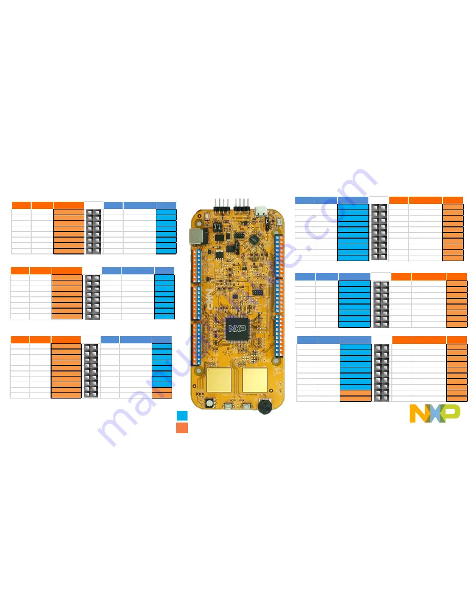
Header/Pinout Mapping for S32K142

Arduino compatible pins
NXP pins

PIN

PORT

FUNCTION

J3

PIN

PORT

FUNCTION

J3-02

PTB6*

GPIO

J3-01

VIN 

J3-04

PTB7*

GPIO

J3-03

IOREF

J3-06

PTE0

GPIO

J3-05

PTA5

RESET

J3-08

PTE9

GPIO

J3-07

3V3

J3-10

PTC5

GPIO

J3-09

5V

J3-12

PTC4

GPIO

J3-11

GND

J3-14

PTA10

GPIO

J3-13

GND

J3-16

PTA4

GPIO

J3-15

VIN

PIN

PORT

FUNCTION

J4

PIN

PORT

FUNCTION

J4-02

PTC7

GPIO

J4-01

PTD4

ADC0

J4-04

PTC6

GPIO

J4-03

PTB12

ADC1

J4-06

PTB17

GPIO

J4-05

PTB0

ADC2

J4-08

PTB14

GPIO

J4-07

PTB1

ADC3

J4-10

PTB15

GPIO

J4-09

PTA6/PTE11/PTA2

ADC4

J4-12

PTB16

GPIO

J4-11

PTC0/PTE10/PTA3

ADC5

J4-14

PTC14

GPIO

J4-13

PTE2

ADC6

J4-16

PTC3

GPIO

J4-15

PTE6

ADC7

PIN

PORT

FUNCTION

J5

PIN

PORT

FUNCTION

J5-02

PTE16

GPIO

J5-01

PTA15/PTD11

ADC8

J5-04

PTE15

GPIO

J5-03

PTA16/PTD10

ADC9

J5-06

PTE14

GPIO

J5-05

PTA1

ADC10

J5-08

PTE13

GPIO

J5-07

PTA0

ADC11

J5-10

VDD

J5-09

PTA7

ADC12

J5-12

GND

J5-11

PTB13

ADC13

J5-14

PTE1

GPIO

J5-13

PTC1

ADC14

J5-16

PTD7

GPIO

J5-15

PTC2

ADC15

J5-18

PTD6

GPIO

J5-17

NC

GPIO

J5-20

PTC15

GPIO

J5-19

NC

N/A

PIN

PORT

FUNCTION

J2

PIN

PORT

FUNCTION

J2-19

PTE10/PTA3

D15/I2C_SDA

J2-20

NC

GPIO

J2-17

PTE11/PTA2

D14/I2C_CLK

J2-18

NC

GPIO

J2-15

ANALOGUE REF

J2-16

PTA14

GPIO

J2-13

GND

J2-14

PTE7

GPIO

J2-11

PTB2

D13/SPI_SCK

J2-12

PTC13

GPIO

J2-09

PTB3

D12/SPI_SIN

J2-10

PTC12

GPIO

J2-07

PTB4

D11/SPI_SOUT

J2-08

PTE8

GPIO

J2-05

PTB5

D10/SPI_CS

J2-06

PTD0

GPIO

J2-03

PTD14

D9/PWM

J2-04

PTD16

GPIO

J2-01

PTD13 

D8/PWM

J2-02

PTD15

GPIO

PIN

PORT

FUNCTION

J1

PIN

PORT

FUNCTION

J1-15

PTC11/PTE8

D7

J1-16

PTE3

GPIO

J1-13

PTC10/PTC3

D6

J1-14

PTD3

GPIO

J1-11

PTB11

D5

J1-12

PTD5

GPIO

J1-09

PTB10

D4

J1-10

PTD12

GPIO

J1-07

PTB9

D3

J1-08

PTD11

GPIO

J1-05

PTB8

D2

J1-06

PTD10

GPIO

J1-03

PTA3

D1

J1-04

PTA17

GPIO

J1-01

PTA2

D0

J1-02

PTA11

GPIO

PIN

PORT

FUNCTION

J6

PIN

PORT

FUNCTION

J6-19

PTA9

D14

J6-20

PTE4

GPIO

J6-17

PTA8

D15

J6-18

PTE5

GPIO

J6-15

PTE12

D16

J6-16

PTA12

GPIO

J6-13

PTD17

D17

J6-14

PTA13

GPIO

J6-11

PTC9

D18

J6-12

GND

J6-09

PTC8

D19

J6-10

VDD

J6-07

PTD8

D20

J6-08

PTC16

GPIO

J6-05

PTD9

D21

J6-06

PTC17

GPIO

J6-03

PTD2

GPIO

J6-04

PTD3

GPIO

J6-01

PTD0

GPIO

J6-02

PTD1

GPIO

J2

J1

J6

J3

J4

J5

*0ohm resistor is not connected

Summary of Contents for S32K142

Page 1: ...EXTERNAL USE REV3 APPLIES FOR S32K142 EVB SCH_29701 REV D C QUICK START GUDE S32K142 EVB...

Page 2: ...Get to Know S32K142 EVB Out of the Box Setup Introduction to OpenSDA Creating a new S32DS project for S32K142 Download Create a project Create a project from SDK example S32DS Debug basics Create a P...

Page 3: ...ion Bus RGB LED S32K142 MCU LIN Communication Bus OpenSDA USB Reset Button OpenSDA MCU OpenSDA JTAG Potentiometer User Buttons Get to know S32K142 EVB J2 Header J1 Header J6 Header J3 Header J4 Header...

Page 4: ...al and debug adapter OpenSDA with support for several industry standard debug interfaces Easy access to the MCU I O header pins for prototyping On chip connectivity for CAN LIN UART SCI SBC UJA1169 an...

Page 5: ...J5 18 PTD6 GPIO J5 17 NC GPIO J5 20 PTC15 GPIO J5 19 NC N A PIN PORT FUNCTION J2 PIN PORT FUNCTION J2 19 PTE10 PTA3 D15 I2C_SDA J2 20 NC GPIO J2 17 PTE11 PTA2 D14 I2C_CLK J2 18 NC GPIO J2 15 ANALOGUE...

Page 6: ...3 Default Reset signal to OpenSDA use to enter into OpenSDA Bootloader mode Reset signal direct to the MCU use to reset S32K142 J107 1 2 2 3 Default S32K142 powered by 12V power source S32K142 powered...

Page 7: ...M0 CH1 Potentiometer PTC14 ADC0_SE12 SW2 PTC12 SW3 PTC13 OpenSDA UART TX PTC7 LPUART1_TX OpenSDA UART RX PTC6 LPUART1_RX CAN TX PTE5 CAN0_TX CAN RX PTE4 CAN0_RX LIN TX PTC3 LPUART0_TX LIN RX PTC2 LPUA...

Page 8: ...t support LPUART Workaround Connect MCU s pin 29 to LIN Phy s LIN_TX trace and MCU s pin 30 to LIN Phy s LIN_RX trace at PCB level This can be done by removing R131 and R130 connecting pad 1 of R132 D...

Page 9: ...EXTERNAL USE 8 S32K142 EVB OUT OF THE BOX...

Page 10: ...ternal 12V power supply By default USB power is enabled with J107 check slide 5 Connect the USB cable to a PC using supplied USB cable Connect other end of USB cable microUSB to mini B port on S32K142...

Page 11: ...ep 1 Power up the Board Is it powered on correctly When powered through USB LEDs D2 and D3 should light green Once the board is recognized it should appear as a mass storage device in your PC with the...

Page 12: ...EXTERNAL USE 11 Step 1 Power up the Board Is it powered on correctly Board is preloaded with a software in which the red blue and green leds will toggle at different rates...

Page 13: ...EXTERNAL USE 12 INTRODUCTION TO OPENSDA...

Page 14: ...et button SW5 4 Plug in a USB cable not included between a USB host and the OpenSDA USB connector labeled SDA 5 Release the Reset button A removable drive should now be visible in the host file system...

Page 15: ...of the srec files to the EVB S32K142 drive The new application should now be running on the S32K142 EVB Starting with v1 03 of the MSD Flash Programmer you can program repeatedly without the need to u...

Page 16: ...EXTERNAL USE 15 INSTALLING S32DS...

Page 17: ...EXTERNAL USE 16 Download S32DS Download S32DS from S32DS for ARM...

Page 18: ...EXTERNAL USE 17 CREATE A NEW PROJECT IN S32 DESIGN STUDIO...

Page 19: ...rst Time Select a Workspace Start program Click on S32 Design Studio for ARM v2 0 icon Select workspace Choose default see below example or specify new one Suggestion Uncheck the box Use this as the d...

Page 20: ...EXTERNAL USE 19 Create New Project Top Menu Selection File New Project...

Page 21: ...EXTERNAL USE 20 Create New Project S32DS Project Project Name Example FirstProject Project Type Select from inside executable or library folder Next...

Page 22: ...EXTERNAL USE 21 Create New Project S32DS Project Select Debugger Support and Library Support Click Finish...

Page 23: ...EXTERNAL USE 22 OpenSDA Configuration To Debug your project with OpenSDA it is necessary to select the OpenSDA in the Debug Configuration Select your project and click on debug configuration...

Page 24: ...EXTERNAL USE 23 OpenSDA Configuration Select the Debug configuration under GDB PEMicro Interface Debugging Click on Debugger tab...

Page 25: ...EXTERNAL USE 24 OpenSDA Configuration Select OpenSDA as the interface if your board is plugged should appear in the Port field Click Apply and debug to finish...

Page 26: ...EXTERNAL USE 25 CREATE AN EXAMPLE FROM SDK...

Page 27: ...26 Creating example from SDK The S32 Design Studio IDE already includes the Software Development Kit for quickly develop applications on S32K1xx devices To create a project using an example go to File...

Page 28: ...EXTERNAL USE 27 Creating example from SDK Go to the S32K14x EAR SDK v0 8 6 Example Projects section and select the example that wants to be used In this example the hello_world is selected...

Page 29: ...L USE 28 Creating example from SDK A new project would be created in the workspace Then click on generate code icon and then on debug as indicated If run correctly the LED should start blinking red an...

Page 30: ...ete documentation of the SDK can be found in C NXP S32DS_ARM_v2018 R1 S32DS S32SDK_S32K14x_EAR_0 8 6 doc Start_here html For more information about the use of the SDK go click on the following link fo...

Page 31: ...EXTERNAL USE 30 DEBUG BASICS...

Page 32: ...ps Three options to start debugger If the Debug Configuration has not been closed click on Debug button on bottom right Select Run Debug or hit F11 Note This method currently selects the desktop targe...

Page 33: ...EXTERNAL USE 32 Debug Basics Step Run Suspend Resume Step Into F5 Step Over F6 Step Return F7 Run Suspend Resume F8...

Page 34: ...EXTERNAL USE 33 Debug Basics View Alter Variables View variables in Variables tab Click on a value to allow typing in a different value...

Page 35: ...EXTERNAL USE 34 Debug Basics View Alter Registers View CPU registers in the Registers tab Click on a value to allow typing in a different value View peripheral registers in the EmbSys Registers tab...

Page 36: ...EXTERNAL USE 35 Debug Basics View Alter Memory Add Memory Monitor Select Base Address to Start at 40000000 View Memory...

Page 37: ...EXTERNAL USE 36 Debug Basics Breakpoints Add Breakpoint Point and Click light blue dot represents debugger breakpoint...

Page 38: ...EXTERNAL USE 37 Debug Basics Reset Terminate Debug Session Reset program counter Terminate Ctl F2...

Page 39: ...EXTERNAL USE 38 CREATE A P E DEBUG CONFIGURATION OPTIONAL...

Page 40: ...EXTERNAL USE 39 New P E debug configuration Click in debug configurations...

Page 41: ...EXTERNAL USE 40 New P E debug configuration Create a new P E launch configuration Click to create a new P E launch Click on the debugger tab...

Page 42: ...EXTERNAL USE 41 New P E debug configuration Select the device Click Apply and debug your application Select device...

Page 43: ...EXTERNAL USE 42 USEFUL LINKS...

Page 44: ...This application note contains a bunch of simple examples of how to use different peripherals S32K1xx community Visit this site for request support on the S32K1xx products you can also look for thread...

Page 45: ......

Reviews: