NXP Semiconductors OM13321 User Manual Download Page 5

UM10709

All information provided in this document is subject to legal disclaimers.

© NXP B.V. 2017. All rights reserved.

User manual

Rev. 2 — 11 August 2017 

5 of 18

NXP Semiconductors

UM10709

PCA9956B demonstration board OM13321

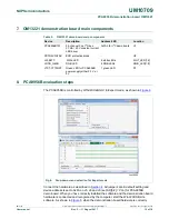
4.3  OM13321 connection to WIN-I2CUSB hardware adapter board

The Win-I2CUSB board should be disconnected from your PC before connecting the 
OM13321 board on to it. The OM13321 board has a 14-pin male connector (CON4) that 
connects to the 14-pin male connector (J1) on the Win-I2CUSB board as shown in 

Figure 2

.

Connect the OM13321 board to the Win-I2CUSB board before connecting the USB cable. 
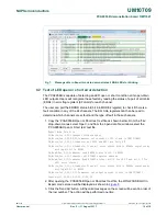
Once the board is connected, connect the USB cable and start the WIN-I2CUSB Lite 
software. You are now ready to evaluate the PCA9956B.
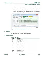
 

Fig 2.

PCA9956B demo board (OM13321) connecting to the WIN-I2CUSB board

Summary of Contents for OM13321

Page 1: ...tract The OM13321 is an add on to 9 pin connector of the NXP I2C demo board 2005 1 or Fm I2C Bus development board This daughter board makes it easy to test and design with the PCA9956B a 24 channel F...

Page 2: ...formation For more information please visit http www nxp com For sales office addresses please send an email to salesaddresses nxp com NXP Semiconductors UM10709 PCA9956B demonstration board OM13321 R...

Page 3: ...pabilities of the PCA9956B On board eight RGB LEDs for visual experience Convenient test points for easy scope measurements and signal access USB interface to the host PC No external power supply requ...

Page 4: ...oftware allows the user to select one of the I2C bus devices on the board from a menu and also provides a Universal mode I2C Expert mode to allow users to create their own I2C bus commands with the sa...

Page 5: ...ould be disconnected from your PC before connecting the OM13321 board on to it The OM13321 board has a 14 pin male connector CON4 that connects to the 14 pin male connector J1 on the Win I2CUSB board...

Page 6: ...V and connected 2 3 for VDD 3 3 V J5 J8 and J9 to select one of the five GND Pull down Floating Pull up and VDD input levels to address inputs AD 0 2 for a maximum of 125 possible programmable I2C bus...

Page 7: ...esistor for SDA on PCA9956B J4 2 pin 1 2 short Short external 1 1 k pull up resistor for SCL on PCA9956B Open no external pull up resistor for SCL on PCA9956B J5 4 2 pin 1 2 1 VDD This 4 2 jumper is u...

Page 8: ...19 2 pin Short This jumper is used to select LED0 supply voltage Open select external 20 V input from J11 to LED0 only Short select either internal 3 3 V when J28 is short or external 20 V when J28 is...

Page 9: ...8 for detecting an LED open error condition in EFLAG register Short normal operation for the RGB_LED8 J30 J32 J34 2 pin Open These jumpers are used to test short circuit for RGB_LED8 J30 is used to se...

Page 10: ...ON2 and convert to 14 pin for new I2C development board Thermal pad 4 8 x 3 mm add thermal vias 5 x 3 0 28 mm diameter with 1 mm pitch with the barrel plated to about 1 0 ounce copper Green LED for Vd...

Page 11: ...to test ch0 VLED up to 20V All jumpers ON when ch0 VLED 3 3V Notes Vf 3 4V for White LED Vf 2 1V for Red LED Vf 3 2V for Green LED Vf 3 2V for Blue LED Open Short test for first three channels 0 2 and...

Page 12: ...set AD 0 2 VDD for PCA9956B demo board When you have correctly installed the software and the demonstration board hardware is connected and recognized by the computer start the Win I2CUSB Lite softwar...

Page 13: ...ite Yes 800 82 04 41 10 04 41 10 Comments set LDRx 01 in LEDOUT register for all green LEDs on for 800 ms FA Write Yes 800 82 10 04 41 10 04 41 Comments set LDRx 01 in LEDOUT register for all blue LED...

Page 14: ...n or Short test text file Expert Mode Data File 00 Write Yes 5 06 Comments software reset FA Write Yes 0 A2 80 80 Comments set current to 50 of max in IREF0 IREF1 FA Write Yes 0 02 05 Comments set LED...

Page 15: ...d line 7 6 To short the J18 and J24 for short circuit test on LED0 and LED1 repeat steps 3 and 4 to find the error report in message line 5 and line 7 9 Support For support please send an e mail to i2...

Page 16: ...1 August 2017 16 of 18 NXP Semiconductors UM10709 PCA9956B demonstration board OM13321 11 References 1 PCA9956B 24 channel Fm I2C bus 57 mA 20 V constant current LED driver Product data sheet NXP Semi...

Page 17: ...in the customer s applications or products or the application or use by customer s third party customer s Customer is responsible for doing all necessary testing for the customer s applications and pr...

Page 18: ...ing started 3 3 1 Assumptions 3 3 2 Static handling requirements 3 3 3 Minimum system requirements 3 3 4 Power requirements 3 4 Installation 4 4 1 I2C demo board 2005 1 and WIN I2CUSB Lite software 4...

Page 19: ...Mouser Electronics Authorized Distributor Click to View Pricing Inventory Delivery Lifecycle Information NXP OM13321 598...

Reviews: