


UM10413
All information provided in this document is subject to legal disclaimers.
© NXP B.V. 2011. All rights reserved.
User manual
Rev. 1 — 16 December 2011
207 of 268
NXP Semiconductors
UM10413
MPT612 User manual
If the RTC is driven by the external 32.786 kHz oscillator, subsequent read operations of
the CTC can yield an incorrect result. The CTC is implemented as a 15-bit ripple counter
so that not all 15 bits change simultaneously. The LSB changes first, then the next, and so
on. Since the 32.786 kHz oscillator is asynchronous to the CPU clock, it is possible for a
CTC read to occur during the time when the CTCR bits are changing, resulting in an
incorrect large difference between back-to-back reads.
If the RTC is driven by the PCLK, the CPU and the RTC are synchronous because both of
their clocks are driven from the PLL output. Therefore, incorrect consecutive reads cannot
occur.
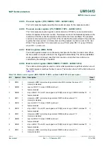
24.6.5 Clock control register (CCR - 0xE002 4008)
The clock register is a 5-bit register that controls the operation of the clock divide circuit.
Each bit of the clock register is described in
.
24.6.6 Counter increment interrupt register (CIIR - 0xE002 400C)
The counter increment interrupt register (CIIR) gives the ability to generate an interrupt
every time a counter is incremented. This interrupt remains valid until cleared by writing a
logic 1 to bit 0 of the interrupt location register (ILR[0]).
Table 195: Clock control register (CCR - address 0xE002 4008) bit description
Bit
Symbol
Description
Reset
value
0
CLKEN
clock enable. If logic 1, time counters are enabled. When logic 0, they
are disabled so that they can be initialized.
n/a
1
CTCRST
CTC reset. If logic 1, the elements in the Clock Tick Counter are reset.
The elements remain reset until CCR[1] is changed to logic 0.
n/a
3:2
-
reserved, user software must not write logic 1s to reserved bits; value
read from a reserved bit is not defined
n/a
4
CLKSRC
if logic 0, the Clock Tick Counter takes its clock from the prescaler, as
on earlier devices in the NXP Embedded ARM family. If logic 1, CTC
takes its clock from the 32 kHz oscillator that is connected to the
RTCX1 and RTCX2 pins (see
Section 24.9 “RTC external 32 kHz
oscillator component selection” on page 216
for hardware details).
n/a
7:5
-
reserved, user software must not write logic 1s to reserved bits; value
read from a reserved bit is not defined
n/a
Table 196: Counter increment interrupt register (CIIR - address 0xE002 400C) bit description
Bit
Symbol
Description
Reset
value
0
IMSEC
if logic 1, an increment of the second value generates an interrupt
n/a
1
IMMIN
if logic 1, an increment of the minute value generates an interrupt
n/a
2
IMHOUR
if logic 1, an increment of the hour value generates an interrupt
n/a
3
IMDOM
if logic 1, an increment of the day of month value generates an interrupt n/a
4
IMDOW
if logic 1, an increment of the day of week value generates an interrupt
n/a
5
IMDOY
if logic 1, an increment of the day of year value generates an interrupt
n/a
6
IMMON
if logic 1, an increment of the month value generates an interrupt
n/a
7
IMYEAR
if logic 1, an increment of the year value generates an interrupt
n/a