


UM10413
All information provided in this document is subject to legal disclaimers.
© NXP B.V. 2011. All rights reserved.
User manual
Rev. 1 — 16 December 2011
106 of 268
NXP Semiconductors
UM10413
MPT612 User manual
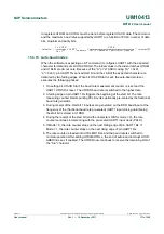
When the receiver FIFO level reaches the programmed trigger level, RTS1 is deasserted
(to a high value). It is possible that the sending UART sends an additional byte after
reaching the trigger level (assuming sending UART has another byte to send) because it
may not recognize the deassertion of RTS1 until after it has begun sending the additional
byte. RTS1 is automatically reasserted (to a low value) once the receiver FIFO has
reached the previous trigger level. The reassertion of RTS1 signals to the sending UART
to continue transmitting data.
If Auto-RTS mode is disabled, bit RTSen controls the RTS1 output of the UART1. If
Auto-RTS mode is enabled, hardware controls the RTS1 output, and the actual value of
RTS1 is copied in bit RTS Control of the UART1. As long as Auto-RTS is enabled, the
value of bit RTS Control is read-only for software.
Example: Suppose UART1 operating in type 550 has the trigger level in U1FCR set to
0x2, if Auto-RTS is enabled, UART1 deasserts the RTS1 output when the receive FIFO
contains 8 bytes (
). The RTS1 output is reasserted when the
receive FIFO reaches the previous trigger level: 4 bytes.
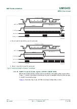
Auto-CTS:
The auto-CTS function is enabled by setting bit CTSen. If auto-CTS is
enabled, the transmitter circuitry in the U1TSR module checks CTS1 input before sending
the next data byte. When CTS1 is active (LOW), the transmitter sends the next byte. To
stop the transmitter from sending the following byte, CTS1 must be released before the
middle of the last stop bit that is currently being sent. In auto-CTS mode, a change of the
CTS1 signal does not trigger a modem status interrupt unless bit CTS Interrupt Enable is
set, however bit Delta CTS in U1MSR is set.
lists the conditions for generating a
Modem Status interrupt.
Fig 22. Auto-RTS functional timing
aaa-000585
start
byte N
stop start bits0..7
stop
start bits0..7
stop
N-1
N
N-1
N-1
N-2
N-2
M+2
M+1
M
M-1
UART1 Rx
RTS1 pin
UART1 Rx
FIFO level
UART1 Rx
FIFO read
Table 112. Modem status interrupt generation
Enable modem
status interrupt
(U1IER[3])
CTSen
(U1MCR[7])
CTS interrupt
enable
(U1IER[7])
Delta CTS
(U1MSR[0])
Delta DCD or
trailing edge RI or
Delta DSR
(U1MSR[3] or U1MSR[2] or (U1MSR[1]))
Modem status
interrupt
0
X
X
X
X
no
1
0
X
0
0
no
1
0
X
1
X
yes
1
0
X
X
1
yes
1
1
0
X
0
no
1
1
0
X
1
yes