


External Bus Interface (EBI)
MPC5644A Microcontroller Reference Manual, Rev. 6
280
Freescale Semiconductor
Address on Data bus multiplexing also supports the 16-bit data bus mode (MCR[DBM]=1) and 16-bit
memories (ORx[PS]=1). The user can select which 16 data signals are used (DATA[0:15] or
DATA[16:31]) by writing the D16_31 bit in the EBI_MCR. For either setting of D16_31, the 16 LSBs of
external address (ADDR[16:31]) are driven onto the selected 16 DATA pins. If additional address lines are
required to interface to the memory, then non-muxed address pins are sometimes (see note below) required
to complete the address space (e.g. ADDR[8:15] are commonly present as non-muxed address pins).
NOTE
The EBI also drives the unused 16 DATA signals with the MSBs of the
external address, zero-padded in front (e.g. when D16_31 bit is set for a
device with 24 ADDR pins, the EBI drives (0b00000000,ADDR[8:15]) on
DATA[0:15]. This allows the device to optionally use DATA[8:15] for the
upper 8 external address lines instead of requiring separate non-muxed
ADDR[8:15] pins. This is relevant primarily for devices that support both
32-bit and 16-bit A/D muxed operation, so therefore have DATA[0:31] pins
present on the device, and in that case are not required to have separate
ADDR pins.
For more details (e.g. timing diagrams), see
Section 14.5.2.12, Address data multiplexing
14.2.3.7
Debug mode
When the MCU is in Debug Mode, the EBI behavior is unaffected and remains dictated by the mode of
the EBI.
14.2.3.8
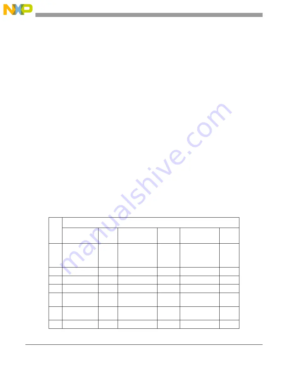
Mode summary table
summarizes pin usage by EBI mode.
Table 14-1. Typical pin usage across supported EBI modes
Pin
EBI Usage Mode
16-bit
non-muxed
1
PCR[PA
]
16-bit muxed
2
PCR[PA]
32-bit muxed
3
PCR[PA
]
0:3
CS[0:3],
ADDR[8:11] or
GPIO[0:3] as
rqd.
4
—
CS[0:3],
ADDR[8:11] or
GPIO[0:3] as rqd.
—
CS[0:3] or
GPIO[0:3] as rqd.
—
8
ADDR[12]
0b001
ADDR[12]
0b001
GPIO[8]
5
0b000
9:10
ADDR[13:14]
0b001
ADDR[13:14]
0b001
WE[2:3]
0b100
11
ADDR[15]
0b001
ADDR[15]
0b001
GPIO[11]
0b000
12:27 ADDR[16:31]
0b001
GPIO[12:27] or
FlexRay usage
0b000 /
0b010
DATA[16:31] /
ADDR[16:31]
6
0b100
28:43 DATA[0:15]
0b001
DATA[0:15] /
ADDR[16:31]
0b001
DATA[0:15] /
ADDR[0:15]
0b001
62
RD_WR
0b001
RD_WR
00b01
RD_WR
0b001
Summary of Contents for MPC5644A
Page 2: ...MPC5644A Microcontroller Reference Manual Rev 6 2 Freescale Semiconductor...
Page 24: ...MPC5644A Microcontroller Reference Manual Rev 6 24 Freescale Semiconductor...
Page 26: ...MPC5644A Microcontroller Reference Manual Rev 6 26 Freescale Semiconductor...
Page 52: ...Introduction MPC5644A Microcontroller Reference Manual Rev 6 52 Freescale Semiconductor...
Page 56: ...Memory Map MPC5644A Microcontroller Reference Manual Rev 6 56 Freescale Semiconductor...
Page 1228: ...Decimation Filter MPC5644A Microcontroller Reference Manual Rev 6 1228 Freescale Semiconductor...
Page 1440: ...FlexCAN Module MPC5644A Microcontroller Reference Manual Rev 6 1440 Freescale Semiconductor...