


Enhanced Queued Analog-to-Digital Converter (EQADC)
MPC5644A Microcontroller Reference Manual, Rev. 6
Freescale Semiconductor
1157
25.7.1.2
Configuring
EQADC
for applications
This section provides an example based on the applications in
. The example describes how to
configure multiple CQueues to be used for those applications and provides a step-by-step procedure to
configure the EQADC and the associated CQueue structures. In the example, the “Fast hardware-triggered
CQueue”, described on the second row of
, will have its commands transferred to CBuffer1;
the conversion commands will be executed by ADC1. The generated results will be returned to RFIFO3
before being transferred to the RQueues in the RAM by the DMAC.
NOTE
There is no fixed relationship between CFIFOs and RFIFOs with the same
number. The results of commands being transferred through CFIFO1 can be
returned to any RFIFO, regardless of its number. The destination of a result
is determined by the MESSAGE_TAG field of the command that requested
the result. See
Section 25.6.2.3, Message Format in EQADC
, for details.
Step One: Setup the CQueues and RQueues.
1. Load the RAM with configuration and conversion commands.
is an example of how
CQueue1 commands should be set.
a) Each trigger event will cause four commands to be executed. When the EQADC detects the
Pause bit asserted, it will wait for another trigger to restart transferring commands from the
CFIFO.
b) At the end of the CQueue, the “EOQ” bit is asserted as shown in
.
c) Results will be returned to RFIFO3 as specified in the MESSAGE_TAG field of commands.
2. Reserve memory space for storing results.
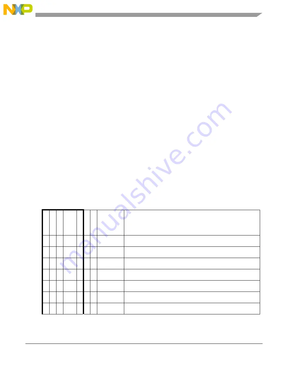
Table 25-76. Example of CQueue Commands
1
Bit #
0
1
2
3
4
5
6
7
8
9 10 11 12 13 14 15 16 17 18 19 20 21 22 23 24 25 26 27 28 29 30 31
Bit
Name
EOQ
P
AUSE
REP
RESER
VED
EB
BN
RESER
VED
MESSAGE
TAG
ADC COMMAND
CMD
1
0
0
0
0
0
1
0
0b0011
Conversion Command
CMD
2
0
0
0
0
0
1
0
0b0011
Conversion Command
CMD
3
0
0
0
0
0
1
0
0b0011
Conversion Command
CMD
4
0
1
0
0
0
1
0
0b0011
2
Configure peripheral device for next conversion sequence
CMD
5
0
0
0
0
0
1
0
0b0011
Conversion Command
CMD
6
0
0
0
0
0
1
0
0b0011
Conversion Command
CMD
7
0
0
0
0
0
1
0
0b0011
Conversion Command
CFIFO Header
ADC Command
Summary of Contents for MPC5644A
Page 2: ...MPC5644A Microcontroller Reference Manual Rev 6 2 Freescale Semiconductor...
Page 24: ...MPC5644A Microcontroller Reference Manual Rev 6 24 Freescale Semiconductor...
Page 26: ...MPC5644A Microcontroller Reference Manual Rev 6 26 Freescale Semiconductor...
Page 52: ...Introduction MPC5644A Microcontroller Reference Manual Rev 6 52 Freescale Semiconductor...
Page 56: ...Memory Map MPC5644A Microcontroller Reference Manual Rev 6 56 Freescale Semiconductor...
Page 1228: ...Decimation Filter MPC5644A Microcontroller Reference Manual Rev 6 1228 Freescale Semiconductor...
Page 1440: ...FlexCAN Module MPC5644A Microcontroller Reference Manual Rev 6 1440 Freescale Semiconductor...