


Universal Serial Bus Interface
MCF5253 Reference Manual, Rev. 1
Freescale Semiconductor
24-149
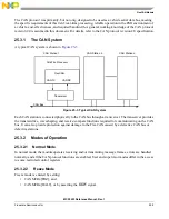
24.12.1.3 Discovery
In a standard EHCI controller design, the EHCI host controller driver detects a Full speed (FS) or Low
speed (LS) device by noting if the port enable bit is set after the port reset operation. The port enable will
only be set in a standard EHCI controller implementation after the port reset operation and when the host
and device negotiate a High-Speed connection (that is, Chirp completes successfully).
The module will always set the port enable after the port reset operation regardless of the result of the host
device chirp result and the resulting port speed will be indicated by the PSPD field in PORTSC
n
.
Therefore, the standard EHCI host controller driver requires an alteration to handle directly connected Full
and Low speed devices or hubs. The change is a fundamental one in that is summarized in
24.12.1.4 Data Structures
The same data structures used for FS/LS transactions though a HS hub are also used for transactions
through the Root Hub. Here it is demonstrated how the Hub Address and Endpoint Speed fields should be
set for directly attached FS/LS devices and hubs:
1. QH (for direct attach FS/LS) – Async. (Bulk/Control Endpoints) Periodic (Interrupt)
•
Hub Address = 0
•
Transactions to direct attached device/hub.
— QH.EPS = Port Speed
•
Transactions to a device downstream from direct attached FS hub.
— QH.EPS = Downstream Device Speed
NOTE
When QH.EPS = 01 (LS) and PORTSC
n
[PSPD] = 00 (FS), a LS-pre-pid
will be sent before the transmitting LS traffic.
Maximum Packet Size must be less than or equal 64 or undefined behavior may result.
2. siTD (for direct attach FS) – Periodic (ISO Endpoint)
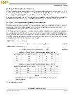
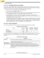
Table 24-93. Functional Differences Between EHCI and EHCI with Embedded TT
Standard EHCI
EHCI with Embedded Transaction Translator
After port enable bit is set following a connection
and reset sequence, the device/hub is assumed to
be HS.
After port enable bit is set following a connection and reset sequence, the
device/hub speed is noted from PORTSCn.
FS and LS devices are assumed to be
downstream from a HS hub thus, all port-level
control is performed through the Hub Class to the
nearest Hub.
FS and LS device can be either downstream from a HS hub or directly
attached. When the FS/LS device is downstream from a HS hub, then
port-level control is done using the Hub Class through the nearest Hub.
When a FS/LS device is directly attached, then port-level control is
accomplished using PORTSCn.
FS and LS devices are assumed to be
downstream from a HS hub with HubAddr=X.
[where HubAddr > 0 and HubAddr is the address
of the Hub where the bus transitions from HS to
FS/LS (that is, Split target hub)]
FS and LS device can be either downstream from a HS hub with HubAddr
= X [HubAddr > 0] or directly attached [where HubAddr = 0 and HubAddr
is the address of the Root Hub where the bus transitions from HS to FS/LS
(that is, Split target hub is the root hub)]
Summary of Contents for MCF5253
Page 1: ...Document Number MCF5253RM Rev 1 08 2008 MCF5253 Reference Manual...
Page 26: ...MCF5253 Reference Manual Rev 1 xxvi Freescale Semiconductor...
Page 32: ...MCF5253 Reference Manual Rev 1 xxxii Freescale Semiconductor...
Page 46: ...MCF5253 Introduction MCF5253 Reference Manual Rev 1 1 14 Freescale Semiconductor...
Page 62: ...Signal Description MCF5253 Reference Manual Rev 1 2 16 Freescale Semiconductor...
Page 98: ...Instruction Cache MCF5253 Reference Manual Rev 1 5 10 Freescale Semiconductor...
Page 104: ...Static RAM SRAM MCF5253 Reference Manual Rev 1 6 6 Freescale Semiconductor...
Page 128: ...Synchronous DRAM Controller Module MCF5253 Reference Manual Rev 1 7 24 Freescale Semiconductor...
Page 144: ...Bus Operation MCF5253 Reference Manual Rev 1 8 16 Freescale Semiconductor...
Page 176: ...System Integration Module SIM MCF5253 Reference Manual Rev 1 9 32 Freescale Semiconductor...
Page 198: ...Analog to Digital Converter ADC MCF5253 Reference Manual Rev 1 12 6 Freescale Semiconductor...
Page 246: ...DMA Controller MCF5253 Reference Manual Rev 1 14 18 Freescale Semiconductor...
Page 282: ...UART Modules MCF5253 Reference Manual Rev 1 15 36 Freescale Semiconductor...
Page 344: ...Audio Interface Module AIM MCF5253 Reference Manual Rev 1 17 46 Freescale Semiconductor...
Page 362: ...I2 C Modules MCF5253 Reference Manual Rev 1 18 18 Freescale Semiconductor...
Page 370: ...Boot ROM MCF5253 Reference Manual Rev 1 19 8 Freescale Semiconductor...