Interfacing an LCD to the MC9S08LC60, Rev. 0
Interfacing the LCD MCU to an LCD Glass
Freescale Semiconductor
14
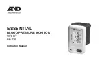
Figure 9. Example Mapping MCU LCD RAM to LCD Glass Alphanumeric Segment Groups
, the MCU LCD RAM registers are shown with both the bit names and the corresponding labels
are provided for the display of the alphanumeric
character “M” in the LCD display. A value of “X” in the table is provided for the bit locations where the
value is not associated with the 13-segment display. For these locations, the bit value is irrelevant. In this
case (for alphanumeric characters in character position 1), these are the bits for the labels “TIME”, “DT”,
and “DT1”.
provides a more detailed tabular form of the decoding from MCU pins to LCD
segments.
Table 5. LCD RAM Values for the Leftmost GD3890P Alphanumeric Character to Display an “M”
LCDRAM0
FP1BP3
“1M”
FP1BP2
“1G”
FP1BP1
“1J”
FP1BP0
“1A”
FP0BP3
“1N”
FP0BP2
“1E”
FP0BP1
“1F”
FP0BP0
“1H”
1
0
1
1
0
1
1
0
LCDRAM1
FP3BP3
“DT”
FP3BP2
“DT1”
FP3BP1
“1C”
FP3BP0
“1B”
FP2BP3
“TIME”
FP2BP2
“1D”
FP2BP1
“1L”
FP2BP0
“1K”
X
X
1
1
X
0
0
0
B
F
A
H
J
K
G
E
N
M
L
C
D
PIN
COM1
COM2
COM3
COM4
5
6
7
8
1H
1A
1K
1B
1F
1J
1L
1C
1E
1G
1D
DT1
1N
1M
TIME
DT
5
6
7
8
FP0
FP1
FP2
FP3
LCD401