


NXP Semiconductors
UM11183
KITFS85SKTEVM evaluation board
UM11183
All information provided in this document is subject to legal disclaimers.
© NXP B.V. 2019. All rights reserved.
User guide
Rev. 2.0 — 20 February 2019
13 / 50
Label
Name
Color
Description
D4
BUCK1
Green
BUCK1 On
D6
BUCK2
Green
BUCK2 On
D7
BUCK3
Green
BUCK3 On
D8
VBOOST
Green
VBOOST On
D9
V
PRE
Green
V
PRE
On
D12
DBG > 8.0 V
Blue
DBG pin voltage > 8.0 V (OTP programming)
D13
RSTb
Red
RSTb asserted (logic level = 0)
D14
INTb
Red
INTb asserted (logic level = 0)
D15
FS0b
Red
FS0b asserted (logic level = 0)
D16
P3V3_KL25
Green
P3V3_KL25 On
D106
PGOOD
Green
PGOOD released
4.3.3 Connectors
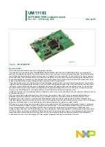
shows the location of connectors on the board.
Figure 14. Evaluation board connector locations
4.3.3.1 V
BAT
connector (J1)
VBAT connects to the board through Phoenix connector (J1).
Table 4. V
BAT
Phoenix connector (J1)
Schematic label
Signal name
Description
J1-1
V
BAT
Battery voltage supply input
J1-2
GND
Ground