
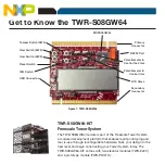


TOWER SYSTEM
Lab Tutorial for TWR-S08GW64
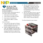
Set Up the TWR-
9S08GW64 Module
Basic steps for the Tower System
hardware installation
For the LCD LAB, the following cards of
the Tower System are required:
1. Tower System Primary Elevator
2. Tower System Secondary Elevator
3. Tower System Serial Module
4. Tower System GW64 Controller
Module
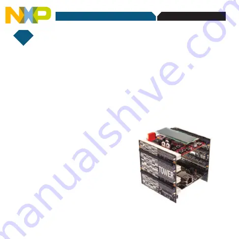
How to Connect:
1. There are four slots each on Primary
and Secondary Elevator card. All four
slots are identical to each other.
2. Take the GW64 Controller card and
insert the PRIMARY connector side in
the Primary Elevator, matching the “B”
marking of the Elevator card and the
controller card in any of the four slots.
3. Take the Serial Module and insert
the PRIMARY connector side in the
Primary Elevator, matching the “B”
marking of the Elevator card and
the Serial Module in any of the three
remaining slots.
4. Take the Secondary Elevator card and
fit it on the other side of the GW64
Controller and the Serial Module card,
again matching the “B” marking so
that it forms a Tower-like structure.
The Tower System is now in place.
STEP
4