NXP Semiconductors Freescale FRDM-CR20A User Manual Download Page 19

Freescale Freedom Development Board FRDM-CR20A User’s Guide, Rev. 0, 04/2015

Freescale Semiconductor, Inc.

19

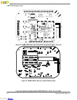
FRDM-CR20A development board

21

1

J6 DNP

HDR 1X2 
TH

HDR 1X2 TH 100MIL SP 339H AU 
98L

SAMTEC

TSW-102-07-G-S

22

1

J7

HDR TH 
1X3

HDR 1X3 TH 100MIL SP 339H AU 
100L

SAMTEC

TSW-103-07-G-S

23

1

LED1

RED

LED RED CLEAR SGL 30MA SMT 
0805

LITE ON

LTST-C171KRKT

24

1

LED2 

CLV1A-FKB
-CJ1M1F1B
B7R4S3

LED RED BL GRN SGL 
50/25/25mA SMT

CREE, INC

CLV1A-FKB-CJ1M1F1
BB7R4S3

25

1

L1 DNP

4.3nH

IND -- 4.3NH@500MHZ 160MA 
2% 0402

MURATA

LQP15MN4N3B02

26

6

L2,L3,L4,L
5,L6,L7 
DNP

10nH

IND -- 0.010uH@100MHZ 350MA 
5% 0402

TDK

MLK1005S10NJT000

27

3

R1,R2,R20 0

RES MF ZERO OHM 1/16W 5% 
0402

ROHM

MCR01MZPJ000

28

3

R4,R13,R1
4

0

RES MF ZERO OHM 1/10W -- 
0603

VISHAY 
INTERTECHNOLOGY

CRCW06030000Z0EA

29

4

R5,R10,R1
1,R12

220

RES MF 220 OHM 1/10W 5% 0603 KOA SPEER

RK73B1JTTD221J

30

3

R6,R7,R8 
DNP

10.0K

RES MF 10.0K 1/16W 1% 
AEC-Q200 0402

VISHAY 
INTERTECHNOLOGY

CRCW040210K0FKE
D

31

9

R15,R16,R
17,R18,R1
9,R21,R22,
R23,R24 
DNP

0

RES MF ZERO OHM 1/16W 5% 
0402

ROHM

MCR01MZPJ000

32

10

SH1,SH2,S
H3,SH4,SH
5,SH6,SH7
,SH8,SH9,
SH10

0

ZERO OHM CUT TRACE 0402 
PADS; NO PART TO ORDER

LAYOUT ELEMENT 
ONLY

LAYOUT ELEMENT 
ONLY

33

3

SW1,SW2,
SW3

TL1015AF1
60QG

SW SPST PB 50MA 12V SMT

E SWITCH

TL1015AF160QG

34

1

S1 DNP

BMI-S-103

SHIELD RF 1032X1032MIL 1 
PIECE

LAIRD 
TECHNOLOGIES

BMI-S-103

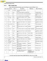
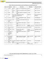
Table 5. Bill of materials (Common parts for all frequency bands) (Sheet 2 of 3)

Item

Qty Reference

Value

Description

Mfg. Name

Mfg. Part Number

Downloaded from

Arrow.com.

Downloaded from

Arrow.com.

Downloaded from

Arrow.com.

Downloaded from

Arrow.com.

Downloaded from

Arrow.com.

Downloaded from

Arrow.com.

Downloaded from

Arrow.com.

Downloaded from

Arrow.com.

Downloaded from

Arrow.com.

Downloaded from

Arrow.com.

Downloaded from

Arrow.com.

Downloaded from

Arrow.com.

Downloaded from

Arrow.com.

Downloaded from

Arrow.com.

Downloaded from

Arrow.com.

Downloaded from

Arrow.com.

Downloaded from

Arrow.com.

Downloaded from

Arrow.com.

Downloaded from

Arrow.com.

Summary of Contents for Freescale FRDM-CR20A

Page 1: ...ill be responsible for reevaluating the end product including the transmitter and obtaining a separate FCC authorization Document Number FRDMCR20AUG Rev 0 04 2015 Contents 1 About this guide 1 1 1 Aud...

Page 2: ...is used with the device The use of a permanently attached antenna or of an antenna that uses a unique coupling to the intentional radiator is considered sufficient to comply with the provisions of thi...

Page 3: ...JESD78 IC Latch Up Test When operating or handling the development boards or components Freescale strongly recommends using at least the grounding wrist straps plus any or all of the following ESD di...

Page 4: ...eld It contains the MCR20AVHM device and all necessary I O connections to connect with the Freedom system Figure 1 shows the FRDM CR20A development board Figure 1 FRDM CR20A The FRDM CR20A development...

Page 5: ...ice wake up SPI communication is enabled in LP mode Provides access to the MCR20AVHM set of GPIOs Figure 2 shows the main board features and Input Output headers for the Freescale FRDM CR20A board Fig...

Page 6: ...tion specific such as a shield card 4 1 1 PCB features The FRDM CR20A board provides the following features The Freescale Freedom development platform form factor Two layer metal 0 062 inch thick FR4...

Page 7: ...es on the Freescale Freedom platform board J6 Header has standard 0 1 in 2 54 mm pin spacing J6 is a 1x2 pin with a cut trace on bottom side Pin headers mounted on the top side of the FRDM CR20A and i...

Page 8: ...Saturation maximum input level 0 dBm Refer to data sheet Sensitivity for 1 packet error rate PER 25 C 802 15 4 102 dBm Refer to data sheet RF Transmitter RF Power Output 35 8 dBm Programmable in steps...

Page 9: ...block diagram 4 2 1 RF performance and considerations The FRDM CR20A development board includes the Freescale MCR20 2 4 GHz transceiver Key specifications for the FRDM CR20A development board are Prog...

Page 10: ...Figure 6 FRDM CR20A RF circuitry 4 2 2 Clocks The FRDM CR20A provides two clocks 32 MHz Reference Oscillator Figure 7 shows the external 32 MHz external crystal Y1 This mounted crystal must meet the...

Page 11: ...resistor provides the means to supply either the IC or board circuits Current measurements can be made by inserting a current meter in place of a designated jumper Connections configurations are descr...

Page 12: ...B circuit The RGB LED circuity offers the following features RGB power supply is P3V3_BRD GPIO driven externally by J4 Header J4 4 Blue J4 5 Green J4 6 Red Optionally a 0 ohm resistor can be populated...

Page 13: ...ctors J1 J2 J3 and J4 are 100 mil pin headers mounted on the top component side supporting the FDRM standard connector Voltage rails VCC_3V3 VCC_5V and V_IN 5 9V are routed via header J3 To avoid dama...

Page 14: ...CLK_OUT D15 Ana Int Table 4 J3 J4 connector J3 J4 Header Pin Number Board Pin Name Description Header Pin Number Board Pin Name Description 1 NC NC 1 VDD_REGD A0 2 IO_REF FRDM xxxxx 3V3 Arduino UNO 5V...

Page 15: ...8535 B FRDM MCR20A C Wednesday November 19 2014 FRDM MCR20A Shield 3 3 ___ ___ X Drawing Title Size Document Number Rev Date Sheet of Page Title ICAP Classification FCP FIUO PUBI SCH 28535 PDF SPF2853...

Page 16: ...ard PCB test points Downloaded from Arrow com Downloaded from Arrow com Downloaded from Arrow com Downloaded from Arrow com Downloaded from Arrow com Downloaded from Arrow com Downloaded from Arrow co...

Page 17: ...view Downloaded from Arrow com Downloaded from Arrow com Downloaded from Arrow com Downloaded from Arrow com Downloaded from Arrow com Downloaded from Arrow com Downloaded from Arrow com Downloaded fr...

Page 18: ...TA GRM155R60J334KE0 1D 12 1 C13 10uF CAP CER 10UF 10V 20 X5R 0603 TAIYO YUDEN LMK107BJ106MALTD 13 1 C14 2 2UF CAP CER 2 2UF 10V 10 X7R 0603 TAIYO YUDEN LMK107B7225KA T 14 2 C16 C17 11pF CAP CER 11pF 5...

Page 19: ...W 1 AEC Q200 0402 VISHAY INTERTECHNOLOGY CRCW040210K0FKE D 31 9 R15 R16 R 17 R18 R1 9 R21 R22 R23 R24 DNP 0 RES MF ZERO OHM 1 16W 5 0402 ROHM MCR01MZPJ000 32 10 SH1 SH2 S H3 SH4 SH 5 SH6 SH7 SH8 SH9 S...

Page 20: ...ART TO ORDER NOTACOMPONENT NOTACOMPONENT 36 3 TP18 TP19 TP20 TPAD_030 TEST POINT PAD 30MIL DIA SMT NO PART TO ORDER NOTACOMPONENT NOTACOMPONENT 37 5 TP21 TP22 TP23 TP2 4 TP25 DNP TEST POINT WHITE TEST...

Page 21: ...RM is also available at the same web site to provide additional design guidance 5 1 Single PCB construction This section describes individual PCB construction details The FRDM CR20A PCBs are two layer...

Page 22: ...pper foil Top and bottom copper layers must be 1 oz copper Plating All pad plating must be Hot Air Levelling HAL 5 4 Solder mask The solder mask must meet the following requirements Solder mask type L...

Page 23: ...s included with the Gerber files are for PCB manufacturing PDF files included are FAB 28535 pdf FRDM Board fabrication drawing GRB 28535 zip FRDM Metal layers solder mask solder paste and silk screen...

Page 24: ...pplication by customer s technical experts Freescale does not convey any license under its patent rights nor the rights of others Freescale sells products pursuant to standard terms and conditions of...

Reviews: