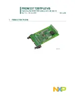
NXP Semiconductors FRDM33772BTPLEVB User Manual Download Page 5

NXP Semiconductors

FRDM33772BTPLEVB

Featuring the MC33772B battery cell controller IC

FRDM33772BTPLEVBUG

All information provided in this document is subject to legal disclaimers.

© NXP B.V. 2018. All rights reserved.

User guide

Rev. 1.0 — 22 June 2018

5 / 17

4.4 Device features

The MC33772B is a battery cell controller IC designed to monitor battery characteristics,

such as voltage, current and temperature. The MC33772B contains all the circuit blocks

necessary to perform synchronous battery cell voltage/current measurement, coulomb

counting, cell temperature measurement and integrated cell balancing. The device

supports the following functions:

Table 1. MC33772B device features

Device

Description

Features

MC33772B

Battery cell controller

5.0 V ≤ VPWR ≤ 30 V operation, 40 V transient

3 to 6 cells management

0.8 mV total cell voltage measurement error

Isolated 2.0 Mbps differential communication or 4.0 Mbps SPI

Addressable on initialization

Synchronized cell voltage/current measurement with coulomb count

Total stack voltage measurement

Seven GPIO/temperature sensor inputs

5.0 V reference supply output with 5 mA capability

Automatic over/undervoltage and temperature detection routable to fault pin

Integrated sleep mode over/undervoltage and temperature monitoring

Onboard 300 mA passive cell balancing with diagnostics

Hot plug capable

Detection of internal and external faults, as open lines, shorts, and leakages

Designed to support ISO 26262 up to ASIL D safety system

Fully compatible with the MC33772 for a maximum of 14 cells

Qualified in compliance with AEC-Q100

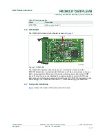
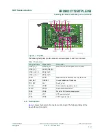
4.5 Board description

The FRDM33772BTPLEVB allows the user to exercise all the functions of the MC33772B

battery controller cell.

Figure 2. Board description

Summary of Contents for FRDM33772BTPLEVB

Page 1: ...FRDM33772BTPLEVB Featuring the MC33772B battery cell controller IC Rev 1 0 22 June 2018 User guide 1 FRDM33772BTPLEVB...

Page 2: ...es and technical support services Should this evaluation kit not meet the specifications indicated in the kit it may be returned within 30 days from the date of delivery and will be replaced by a new...

Page 3: ...com FRDM33772BTPLEVB 2 On the Overview tab locate the Jump To navigation feature on the left side of the window 3 Select the Get Started link 4 Review each entry in the Get Started section 5 Download...

Page 4: ...information is digitally transmitted to a microcontroller for processing The evaluation board can be used in conjunction with a transceiver physical layer transformer driver MC33664 to convert MCU SPI...

Page 5: ...V transient 3 to 6 cells management 0 8 mV total cell voltage measurement error Isolated 2 0 Mbps differential communication or 4 0 Mbps SPI Addressable on initialization Synchronized cell voltage cu...

Page 6: ...igure 3 Figure 3 VCOM LED The VCOM LED indicates when the device is in normal mode Upon reset the MC33772B enters into normal mode VCOM turns on If there is no activity on the bus after a timeout peri...

Page 7: ...gnal name Description RTDX_IN_N SI RDTX_IN RTDX_IN_P SCLK RTDX_IN RTDX_OUT_N RTDX_OUT RTDX_OUT_P RTDX_OUT Measures the isolated pulse communication FAULT FAULT Measures the fault detection sent by the...

Page 8: ...put with external LPF resistor Cell balance 4 3 common Terminate to cell 4 and 3 common pin X1 27 X1 28 CT_2 CB_3 CB_2 Cell pin 2 input with external LPF resistor Cell balance driver Terminate to cell...

Page 9: ...VB supports current sense function with off board shunt resistor The off board shunt resistor shall be connected between X1 31 IS_P and X1 32 IS_N On board current sensing filter and protection circui...

Page 10: ...Configuring the hardware 6 1 Battery stack connection A minimum of 3 cells and a maximum of 6 cells can be monitored NXP provides a 6 cell battery emulator board BATT 6EMULATOR This board provides an...

Page 11: ...ev 1 0 22 June 2018 11 17 Figure 7 Battery stack connection 6 2 Jumper connection One hand soldered jumper JP11 on the EVB is used to set the GPIO0 pin input In position 1 2 default the NTC NTC0 is co...

Page 12: ...eserved User guide Rev 1 0 22 June 2018 12 17 6 3 TPL communication connection In a high voltage Isolated application with a daisy chain configuration up to 15 FRDM33772BTPLEVB boards may be connected...

Page 13: ...in Table 5 Table 5 Off board NTC configuration Remove Short Short Connect off board NTC between NTC0 NTC0 JP28 JP29 J9 1 2 NTC1 NTC1 JP26 JP27 J9 3 4 NTC2 NTC2 JP24 JP25 J9 5 6 NTC3 NTC3 JP22 JP23 J9...

Page 14: ...der battery pack emulator kit with shunt for current sense FRDM33664BEVB EVB for MC33664ATL Isolated Network High Speed Transceiver 8 References 1 Board summary page nxp com FRDM33772BTPLEVB 2 Product...

Page 15: ...iability related to any default damage costs or problem which is based on any weakness or default in the customer s applications or products or the application or use by customer s third party custome...

Page 16: ...6 17 Tables Tab 1 MC33772B device features 5 Tab 2 Board description 6 Tab 3 Test points 7 Tab 4 Cell connector X1 8 Tab 5 Off board NTC configuration 13 Tab 6 Bill of materials 14 Tab 7 Revision hist...

Page 17: ...Kit contents packing list 3 3 2 Required equipment 3 4 Getting to know the hardware 3 4 1 Board overview 3 4 2 Board features 4 4 3 Block diagram 4 4 4 Device features 5 4 5 Board description 5 4 6 V...

Reviews: