


EVB-VF522R3 Platform User’s Guide, Rev. 0, 11/2014
24
Freescale Semiconductor, Inc.
User I/O and control
13.4.1
Slave mode
This is a default mode of operation. This means that the DSP “firmware” is loaded to the DSP via the MCU
SPI0 (PCS0) after boot.
13.4.2
Master mode
In this mode, using the dedicated debug header (P10) and DSP vendor’s programming tool and with a
properly connected “Chip Enable” of the dedicated Flash (see
Table 15
for the jumper J3 settings), the
code for the DSP is loaded into the Flash, and the DSP will boot from it rather than the MCU SPI signals.
The SPI communication with the MCU, however, can still be configured such that the DSP acts as a Slave,
i.e. all the necessary control (volume, effects, tone control, and so on) can still be controlled via the MCU.
Refer to the DSP documentation for details about its operation, programming, and configuring.
14 User I/O and control
There are various modules (available separately), switches, LEDs, connectors, and headers on the EVB as
described in this section:
•
0.1” headers for MCU GPIO signals not used elsewhere (P11, P14),
•
Potentiometer connected to the Vybrid ADC input (RV1),
•
Two incremental encoders (SW1, SW2),
•
Four dedicated station preset push buttons (SW3 to SW6),
•
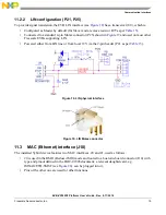
MLB daughtercard connector (P22),
•
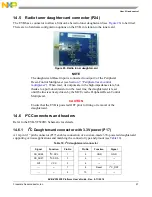
Radio tuner daughtercard connector (P13),
•
I
2
C daughtercard connector (P17),
•
Generic CD header (P18),
•
Bluetooth daughtercard connector (J5).
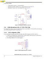
14.1
GPIO Headers (P11, P14)
There are two 0.1” pitch headers on the EVB for connecting to analog (P11) and digital (P14) GPIO
signals, which are not used to directly drive other peripherals on the EVB (see
).
Table 6. Connector P11 (analog)
Signal
Pin No
Pin No
Signal
ADC0SE8
1
2
ADC1SE8
ADC0SE9
3
4
ADC1SE9
DACO0
5
6
DACO1
REF_GND
7
8
REF_GND