


AN10365_3
© NXP B.V. 2008. All rights reserved.
Application note
Rev. 03 — 22 April 2008
17 of 24
NXP Semiconductors
AN10365
Surface mount reflow soldering description
will also reduce the local temperature. Hot spots, on the other hand, are found in areas
with few components, or only the smallest components, and with little Cu. Finally, the
board dimensions, and the board orientation in the oven, may also affect the location of
hot and cold spots.
The temperature of the hot spot on a board must be lower than the upper limit of the peak
temperature. Similarly, the temperature of the cold spot must be higher than the lower limit
of the peak temperature.
In
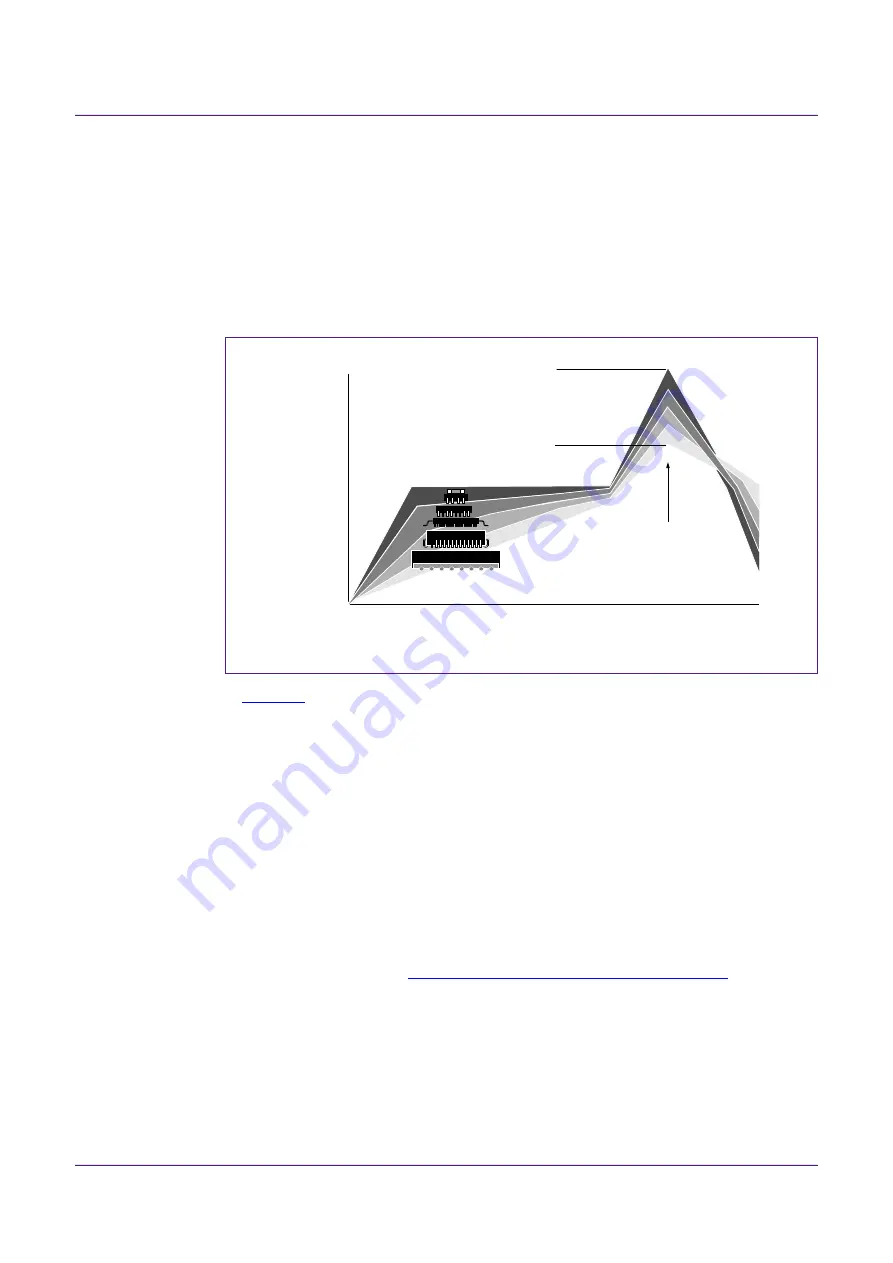
, the grey band with the large component represents cold spots, and the dark
band, at the top, with the smallest component, represents hot spots. In both cases, the
graph first represents a component body temperature, measured at the top of the body. In
the preheat phase, the hot spots will heat up rapidly to a temperature lower than the
melting point of the solder alloy. They may remain at this temperature for a while. Note,
however, that small solder paste deposits should not remain at an intermediate
temperature for so long that their activator runs out: for small solder paste deposits, a fast
temperature profile is preferred. The cold spots on the board will warm up far more slowly.
The oven settings should be planned so that the cold as well as the hot spots will have
reached roughly the same temperature by the end of the preheat phase.
The second phase in the reflow profile is the reflow zone, in which the solder melts and
forms soldered joints. The minimum peak temperature, which all solder joints in the cold
as well as the hot spots must reach, depends on the solder alloy. However, no region on
the board may surpass a maximum peak temperature, as this would result in component
and/or board damage. See
Section 3 “Moisture sensitivity level and storage”
for more
information. Even if the cold and hot spots at the start of the reflow phase have roughly the
same temperature, the hot spots will reach a higher peak temperature than the cold spots.
Yet, both the hot spots and the cold spots must lie within the allowed peak temperature
range. This may require some tweaking of the oven temperature settings and conveyor
belt speeds. In some cases, the board layout may have to be optimized to limit the
temperature difference between the cold and the hot spots.
Fig 16. Temperature profiles for large and small components
001aac844
temperature
time
minimum peak temperature
= minimum soldering temperature
maximum peak temperature
= MSL limit, damage level
peak
temperature