CONFIGURATION INSTRUCTIONS
The NV-ET1804 TBus transmitter delivers high bandwidth encrypted Ethernet signals over virtually any kind of wire (Coax, UTP, STP, Un-twisted
wire, etc.). To provide utmost signal integrity and security, the NV-ET1804 transceivers
must be configured
to communicate exclusively with other
transceivers within their
TBus Network Group
. This group typically consists of one or more remote Transmitters, typically located at the IP camera
and one Receiver, typically located at the control-room. Transmitters may be the NV-ET1801 or NV-ET1804. The Receiver may be the NV-ET1801,
NV-ER1804, NV-ER1808i, or NV-ER1816i.
Before functioning on the network,
each NV-ET1804 must learn which other transceivers are to be part of that group
. This simple process
is called Joining. It is recommended that transceivers in each Network Group be configured
prior to deployment
using these instructions:
Step One: Gather Materials
• All 1800 series Transceivers
• Device labels
• RJ45 patch-cord
• IP Network Documentation Log
• Small paper-clip, partially straightened
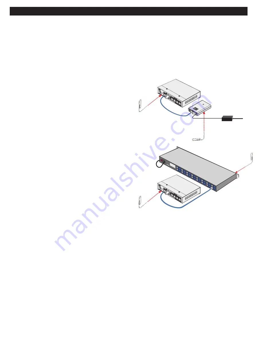
Step Two: Connect Hardware
• Remove and discard the “Configure Before Use” labels.
• Use an RJ45 or BNC patch-cord to connect the TBus ports
of two Transceivers.
CAUTION: Never connect the RJ45 TBus port to an
RJ45 ethernet port
.
• Apply power to one of the TBus devices.
• The blue POWER LED on each Transceiver will blink for 8 seconds and
then go on.
• After 20 seconds, verify that the green TBus Link LED on each transceiver is off.
If a TBus Link LED is on, the Transceiver has been previously joined.
Perform the un-joining process below before proceeding.
Step Three: Joining
• On Transceiver #1, using the straightened paper-clip, momentarily depress and release
the small JOIN push-button located on the bottom of the unit. Its blue Power LED
will begin blinking.
• Depress and release the same push-button on the Transceiver #2. Its blue
Power LED will begin blinking.
• Both Transceivers have now entered
Join Mode
. They will find each other
and establish encrypted communication. In about 10 seconds, the blue Power
LEDs on both Transceivers will return to a steady on condition, and
their green TBus Link LEDs will illuminate, indicating a successful
Join
.
• One TBus Link LED will remain on solid. The other may wink with data.
Step Four: Adding Transceivers
(if required)
• Disconnect Transceiver #1 and replace it with a new un-joined
Transceiver.
• Repeat steps two and three to add additional Transceivers to the same
Network Group.
Step Five: Documentation
• Label the configured Transceivers with a unique Network Group ID of your choice.
This will help you identify them after they have been deployed.
• Record this Network Group information in your IP Network Documentation Log:
• Camera Number
• Camera-end NVT Transceiver MAC Address
• Camera Position/Location
• NVT Transceiver Network Group Name
• Camera Make & Model
• Control Room NVT Transceiver MAC Address
• Camera MAC & IP Address
• Control Room Router Port Number
• Camera Login & Password
This log may include essential documentation which will help you identify all system devices during and after deployment. The NV-ER1808i and
NV-ER1816i user interfaces have data-entry fields for this purpose.
Un-Joining a Transceiver
If you need to move a Transceiver from one Network Group to another, it must first un-learn its
previous Network Group and be returned to an un-joined state. Do this by:
• Apply power.
• The blue POWER LED on each Transceiver will blink for 8 seconds and then go on.
• Using the straightened paper-clip, depress the small JOIN push-button until the blue Power LED goes off (about 13 seconds).
• Un-joining is now complete.
If you are not sure that un-joining has been successful, remove and then re-apply power, and repeat.
Page 3 of 14
10/
100 P
oE
+
56VDC
Transceiver #1
Transceiver #2
56V Power Supply
J
oi
n
B
u
tt
o
n
Joi
n B
utt
on
Transceiver #1
Transceiver #2
Joi
n B
utto
n
Join Button


