NVIS AVCU User Manual Download Page 11


Advanced Video Control Unit (AVCU) User Guide


11

     |  www.nvisinc.com


Figure 13: The Connection Tab 


POSITION ADJUSTMENT 

You  might  need  to  adjust  horizontal  centering  of  the  image that  appears,  depending  on  which 
video  format  you  are  using.  Pixel  screen  position  is  adjusted  for  standard  analog  video  at  the 
factory  (unless  otherwise  requested). If  pixel  screen  position  is  improperly  adjusted,  horizontal 
wrapping can occur. 


To move the displayed image left or right: 


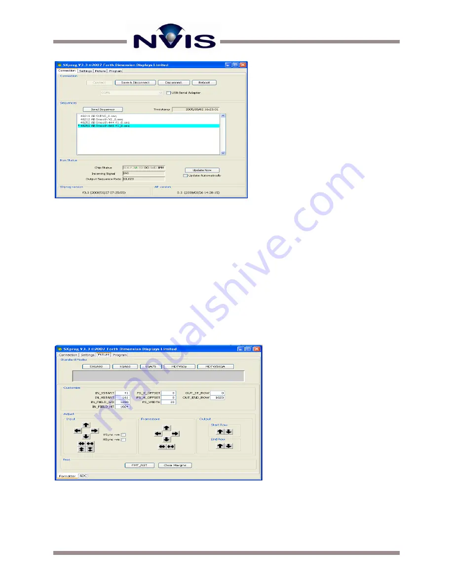
Click on the Picture tab to display the dialog box shown in Figure 14.


  Adjust the 

IN_HSTART

 value to shift the horizontal center left or right. 


Figure 14: The Picture Tab 


Summary of Contents for AVCU

Page 1: ......

Page 2: ...nced Video Control Unit 3 Step by Step Setup Procedures 4 Configuring the AVCU 5 Automatic Video Detection 5 Navigating the AVCU Interface 5 Adjusting Brightness 6 Setting AVCU Preferences 7 Using SXP...

Page 3: ...TROL UNIT The AVCU accepts the video signal from the image generator and provides the correct sync and voltage information to the microdisplays in the head mounted display The AVCU design supports mul...

Page 4: ...ich includes the universal power supply into the AVCU and into 110 220V AC source Connect your video cable s to the computer and to the AVCU Connect an optional external monitor from the AVCU two exte...

Page 5: ...r in this guide NAVIGATING THE AVCU INTERFACE The front of the AVCU has an LCD screen that displays various settings and messages Next to the LCD reside three buttons used for navigation and toggling...

Page 6: ...n for both eyes will be displayed Figure 8 shows and example of the video detection banner In the example a DVI signal is detect on the left channel as indicated by the x Figure 8 Video Detection Disp...

Page 7: ...one by pressing buttons to scroll through the various settings You can hit the Enter button to change a setting In Figure 11 the DAC output setting is selected The pointy brackets on the first line of...

Page 8: ...nputs for analog signals If this is the case the automatic video detection circuitry will fail to detect incoming video signals To set up the video inputs correctly one of the manual analog settings w...

Page 9: ...efault two files with the hex extension are placed in the following directory folder path or similar based on your specific installation C Program Files SXprog User Code Select both the AP hex and BP...

Page 10: ...ctor on the AVCU Launch the SXprog application Before starting make sure you have the new color sequence file loaded into the following directory folder path or similar based on your specific installa...

Page 11: ...ormat you are using Pixel screen position is adjusted for standard analog video at the factory unless otherwise requested If pixel screen position is improperly adjusted horizontal wrapping can occur...

Page 12: ...in regions of the database that contain transitioning color gradients or textures with many gray levels This situation is caused by the time delay between modulating for the first and last bit of a gi...

Page 13: ...native bits per color with 4 bit dither boost Once you ve set the dithering configuration you need to go to the Sequence screen to select the appropriate color sequence for your dithering configuratio...

Page 14: ...to force the AVCU to VGA mode There are two such modes depending if you have a single input or dual Consult Configuring the AVCU for more information Digital video configuration issues should be rare...

Page 15: ...NVIS Inc 11495 Sunset Hills Road Ste 106 Reston VA 20190 www nvisinc com 571 201 8095...

Reviews: