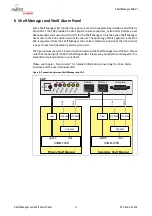


Shelf Manager ACB-VI
Shelf Manager Connectors
25
R1.2, March 2018
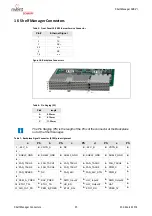
16 Shelf Manager Connectors
Table 5: Front Panel 10/100 Ethernet Service Connector
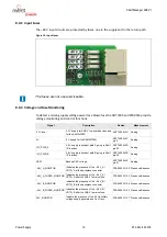
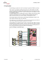
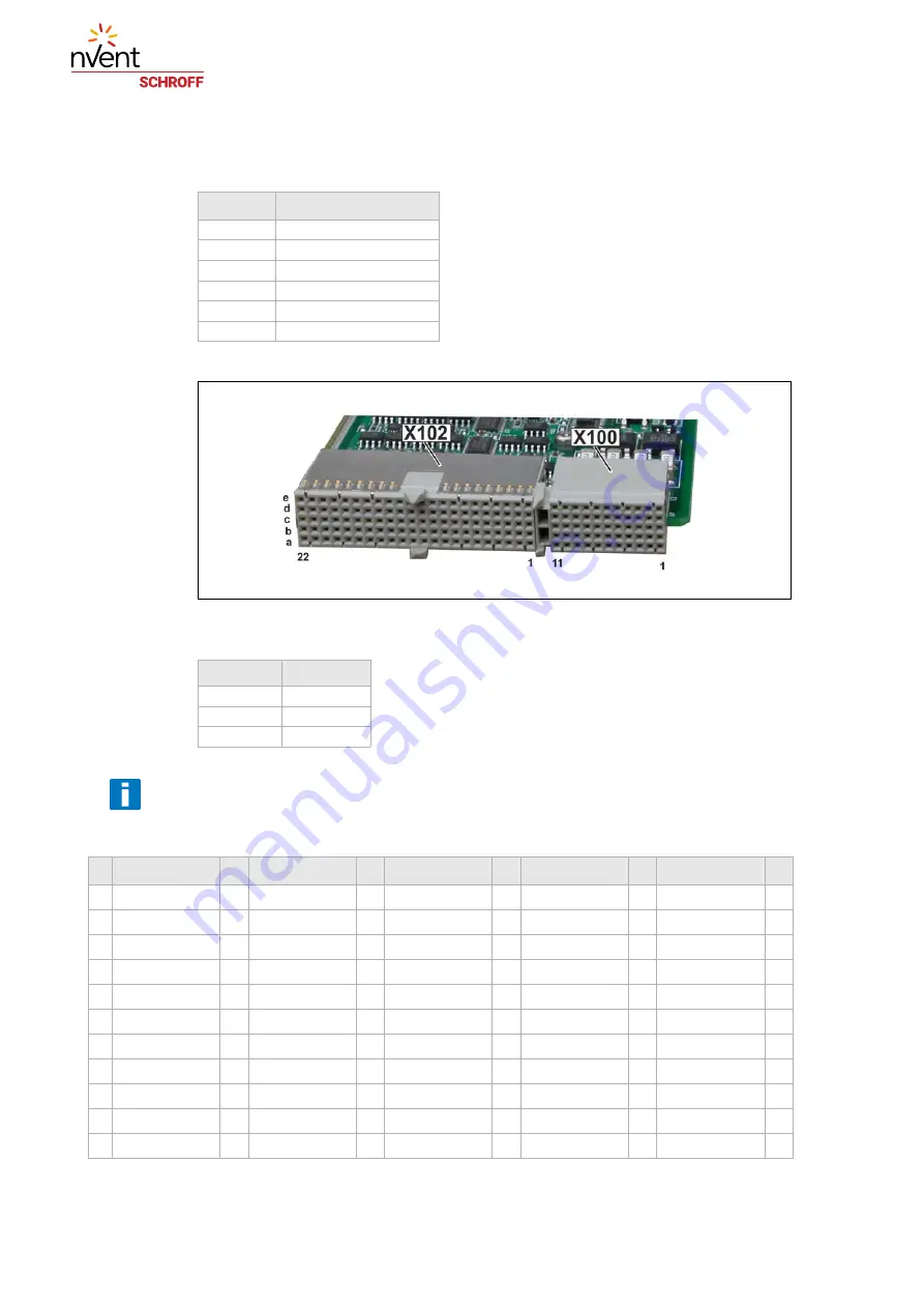
Figure 18: Backplane Connectors
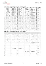
Table 6: Pin Staging (PS)
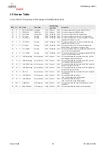
Table 7: Backplane Signal Connector (X100) pin assignment
Pin #
Ethernet Signal
1
TX+
2
TX-
3
RX+
4, 5
n.c.
6
RX-
7, 8
n.c.
Pin#
length
A
8.25 mm
B
9.75 mm
C
11.25 mm
The Pin Staging (PS) is the length of the Pins of the connector at the Backplane
not at the Shelf manager.
a
PS
b
PS
c
PS
d
PS
e
PS
1
-48 V_A
B
VRTN_A
B
NC
B
-48 V_B
B
VRTN_B
B
2
-
-
-
-
-
3
SHELF_GND
B
SHELF_GND
B
SHELF_GND
B
SHELF_GND
B
SHELF_GND
B
4
-
-
-
-
-
5
FAN_TACH0
A
FAN_TACH1
A
FAN_TACH2
A
FAN_TACH3
A
FAN_TACH4
A
6
FAN_TACH5
A
FAN_TACH6
A
FAN_TACH7
A
FAN_TACH8
A
PWM_C
A
7
FAN_SPEED
A
NC
A
FAN_24V
A
FAN_24V_RTN
A
PWM_E
A
8
-
-
-
-
-
9
PEM_A_PRES
A
SAP_PRES
A
SWR_Input#
A
HLY_Input#
A
SWR_Output#
A
10
A
ETH1_TX-
A
HS_EN
A
HLY_Output#
A
HA7
A
11
AIR_FILT_PR
A
PEM_B_PRES
A
A
ETH1_RX-
A
PRES_1#
A


