Nuvoton Nu-Link2-Pro User Manual Download Page 57

Nu-Link2-Pro Debugger and Programmer 


Mar. 13, 2020 

Page 

57

 of 77 

Rev 1.00 


NU

-LINK

2

-P

RO

 D
E

B

UG

G

E

R

 a

nd
 P

RO

G

RA

MM

E

R U

S

E

R

 M

A

NUA

L


Ma
k

er Nu

-m

be
d

 NUC

47

Us
er Man

ua


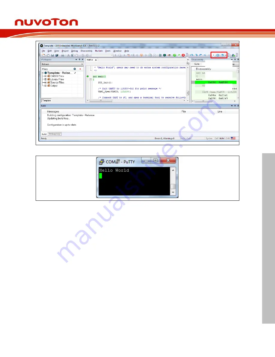
Figure 5.2-34 IAR EWARM Debug Mode 


Figure 5.2-35 Debug Message on Serial Port Terminal Windows 

1 2 3

1. Go

3. Reset

2. Break

Summary of Contents for Nu-Link2-Pro

Page 1: ...tual property of Nuvoton Technology Corporation and shall not be reproduced without permission from Nuvoton Nuvoton is providing this document only for reference purposes of NuMicro microcontroller ba...

Page 2: ...nition and Function Connection 15 ICE Programming Connection 15 Virtual COM Connection 16 Automatic IC Programming Connection 17 Bridge Interface Pin Definition and Function Connection 19 UART Connect...

Page 3: ...Installing the Nu Link2 Pro Driver 38 5 INSTALLATION AND SETUP 39 Connecting to the Nu Link2 Pro 39 Software Setup 40 ICP Tool 40 Keil MDK 44 IAR EWARM 53 NuEclipse GCC 58 ISP Tool 65 More Features o...

Page 4: ...on Diagram for PWM 25 Figure 3 3 7 Bridge Interface Connection Diagram for ADC 26 Figure 3 3 8 Bridge Interface Connection Diagram for GPIO 27 Figure 3 4 1 ETM Interface Connection Diagram for SWD and...

Page 5: ...ing Information Dialog 51 Figure 5 2 25 Breakpoint setting and Execution 52 Figure 5 2 26 Options Selection 53 Figure 5 2 27 IAR EWARM Target Chip Selection 53 Figure 5 2 28 Set IAR EWARM as Third Par...

Page 6: ...to any device of ISP Tool 65 Figure 5 2 49 ISP Firmware Sample Code Project 66 Figure 5 2 50 Boot from LDROM Setting in Keil ISP Firmware Project 67 Figure 5 2 51 Connect to Target Chip with SPI Inte...

Page 7: ...le 3 3 6 Bridge Interface Corresponding Pin for CAN BUS 25 Table 3 3 7 Bridge Interface Corresponding Pin for PWM 26 Table 3 3 8 Bridge Interface Corresponding Pin for ADC 27 Table 3 3 9 Bridge Interf...

Page 8: ...one ICP programmer It also provides a control bus interface that can connect to Automated IC programming system The programming process can be triggered by ICP Programming tool Physical button or Auto...

Page 9: ...Start button Automatic IC programming system connector Control Bus Powered by Micro USB or target powered via SWD interface Support In System Programming ISP Via multi interfaces bridge Supports PC co...

Page 10: ...USB cable 3 ETM cable 4 SWD cable 5 Bridge cable Figure 2 1 1 Nu Link2 Pro Full Kit Contents Figure 2 1 1 shows the contents of Nu Link2 Pro full kit Nu Link2 Pro main body 2952mil x 1968mil x 688mil...

Page 11: ...Figure 2 2 1 shows the main components and connectors from the front side of Nu Link2 Pro PCBA The following lists components and connectors from the front view Main Chip M48SKIDAE Micro SD Card Slot...

Page 12: ...the Nu Link2 Pro profile and connector overview the following lists of function brief description USB Connector CON5 USB Flash Drive for ICP Offline Programming Micro USB Connector J2 Micro USB port...

Page 13: ...peration status of the Nu Link2 Pro Nu Link2 Pro Operation Status Status LED ICE ICP Red Green Boot Flash 3 Flash 3 Flash 3 Flash 3 One Nu Link2 Pro selected to connect Flash 3 Flash 3 Flash 3 On ICE...

Page 14: ...2 RX SCL CON6 3 CON6 4 SDA SS CON6 5 CON6 6 CLK MOSI CON6 7 CON6 8 MISO RS485_A CON6 9 CON6 10 RS485_B CAN_H CON6 11 CON6 12 CAN_L ADC CON6 13 CON6 14 VCC33 PWM CON6 15 CON6 16 VCC33 GPIO0 CON6 17 CON...

Page 15: ...Control Bus signals for IC Programmer For details please refer to section 6 3 ICE_DAT CON4 3 Serial Wired Debugger Data pin START CON4 4 START is Control Bus signals for IC Programmer For details ple...

Page 16: ...responding to the Target Board VCC CON4 1 VCC ICE_DAT CON4 3 ICE_DAT ICE_CLK CON4 5 ICE_CLK RESET CON4 7 RESET VSS GND CON4 9 VSS GND Table 3 2 2 SWD Interface Corresponding Pin for ICE Virtual COM Co...

Page 17: ...et Board VCC CON4 1 VCC PASS TX CON4 8 UART_RX VSS GND CON4 9 VSS GND FAIL RX CON4 10 UART_TX Table 3 2 3 SWD Interface Corresponding Pin for Virtual COM Automatic IC Programming Connection The Nu Lin...

Page 18: ...VCC START NC PASS RX FAIL TX BUSY Figure 3 2 3 SWD Interface Connection Diagram for Automatic IC Programming Pin Name Pin Number Pin Corresponding to the Target Board VCC CON4 1 VCC 1 BUSY CON4 2 BUS...

Page 19: ...r Out Slave In MISO CON6 8 SPI MISO Master In Slave Out RS 485A CON6 9 RS 485 Data plus signal RS 485B CON6 10 RS 485 Data minus signal CANH CON6 11 CAN BUS Data plus signal CANL CON6 12 CAN BUS Data...

Page 20: ...ily Target Board Figure 3 3 1 Bridge Interface Connection Diagram for UART Pin Name Pin Number Pin Corresponding to the Target Board TXD CON6 1 RXD 1 RXD CON6 2 TXD 1 VCC33 CON6 14 VCC 1 VCC33 CON6 16...

Page 21: ...SS TXD RS485A MOSI CNAH GPIO1 ADC GPIO0 PWM SDA CLK RXD RS485B MISO CNAL VSS GND VDD33 VSS GND VDD33 NuMicro Family Target Board Figure 3 3 2 Bridge Interface Connection Diagram for I2C Pin Name Pin N...

Page 22: ...5 CLK CON6 6 MOSI CON6 7 and MISO CON6 8 Figure 3 3 3 presents how to connect the target board to use SPI function and Table 3 3 4 shows the pin corresponding to the target board Bridge Micro USB NuMi...

Page 23: ...tion by UART The RS 485 connection pins are VCC33 CON6 14 and CON6 16 VSS CON6 18 and CON6 20 RS485A CON6 9 and RS485B CON6 10 Figure 3 3 4 presents how to connect the target board to use RS 485 funct...

Page 24: ...The Nu Link2 Pro provides one channel CAN BUS function for monitor mode receive information and print out information by UART The CAN BUS connection pins are VCC33 CON6 14 and CON6 16 VSS CON6 18 and...

Page 25: ...ro Bridge interface Table 3 3 6 Bridge Interface Corresponding Pin for CAN BUS PWM and Capture The Nu Link2 Pro provides one channel PWM function for user flexible planning The PWM connection pins are...

Page 26: ...2 Pro Bridge interface Table 3 3 7 Bridge Interface Corresponding Pin for PWM ADC Connection The Nu Link2 Pro provides one channel ADC function for user flexible planning The ADC connection pins are V...

Page 27: ...3 3 8 Bridge Interface Corresponding Pin for ADC GPIO Connection The Nu Link2 Pro provides two channel GPIO function for user flexible planning The GPIO connection pins are VCC33 CON6 14 and CON6 16...

Page 28: ...n Number Pin Corresponding to the Target Board GPIO0 CON6 17 GPIO or Application side 1 GPIO1 CON6 19 GPIO or Application side 1 VCC33 CON6 14 VCC 1 VCC33 CON6 16 VCC 1 VSS GND CON6 18 VSS GND VSS GND...

Page 29: ...pin GND CON3 5 Ground NC CON3 6 NC KEY CON3 7 A key pin to properly orient the connector NC CON3 8 NC GND CON3 9 Ground RESET CON3 10 IC reset pin Nu Link2 Pro will automatically reset the target IC...

Page 30: ...provides ETM function for capturing execution steps of microprocessor on the target board and ETM will display them a readability format Figure 3 4 1 presents how to connect the target board to use E...

Page 31: ...nd PROGRAMMER USER MANUAL M m U SWD NuMicro Family Target Board ICE_DAT ICE_CLK RESET VSS GND VCC START NC PASS RX FAIL TX BUSY 1 USB Flash drive 2 Micro SD card Micro USB 3 SPI Flash ICP Programming...

Page 32: ...er can add breakpoints in the code for debugging During the real time simulation of the Nu Link2 Pro the chip simulation will be stopped at a specific breakpoint Figure 4 1 1 shows the breakpoint sett...

Page 33: ...Debug Mode The System Viewer for CLK is shown in Figure 4 1 3 where the lower side shows the register address and description and the upper side shows the register value Detailed Operation Double cli...

Page 34: ...be output through UART to the debug window by the Nu Link2 Pro That is the message is output without the GPIO Figure 4 1 4 shows the debug messages in the UART 1 form which are the messages output by...

Page 35: ...igure 4 1 4 Step 4 Press F5 to program the target chip and the debug messages are output to the UART 1 form3 Figure 4 1 4 Semihost Options in Keil MDK Debug Mode Embedded Trace Macrocell ETM Nu Link2...

Page 36: ...for mass production since the original code or firmware file does not need to be delivered and only the Nu Link2 Pro is needed for mass production In addition the Nu Link2 Pro supports Limited Offlin...

Page 37: ...ports UART I2C SPI RS 485 and CAN BUS Table 5 2 2 show the connection method of each interface and please refer to the section 5 2 5 for ISP online programming details Software Serial Number SN The So...

Page 38: ...voltage programming function by which the development software tool can adjust the SWD port voltage as 1 8 V 2 5 V 3 3 V or 5 0 V As shown in Figure 3 2 1 the pins that can be controlled include VCC I...

Page 39: ...program the target chip through an USB The user can plug the Nu Link2 Pro into an USB port of a PC directly or connect using the USB connector About connection method please refer to section 3 2 for d...

Page 40: ...iled software operation refer to the related user manuals ICP Tool 1 Download and install Nuvoton NuMicro ICP Programming Tool 2 Open the ICP Tool specify the UI language and target chip and then clic...

Page 41: ...ed adapter with the host as shown in Figure 5 2 3 When a Nu Link2 Pro is selected for connection the Status LED starts blinking Figure 5 2 3 Select One Nu Link2 Pro 6 Click Option in the Programming s...

Page 42: ...eck button is clicked At this time the user cannot program any chip but can use the offline programming to save the offline programming information in the Nu Link2 Pro Figure 5 2 6 Nu Link2 Pro Connec...

Page 43: ...Pro Debugger and Programmer Mar 13 2020 Page 43 of 77 Rev 1 00 NU LINK2 PRO DEBUGGER and PROGRAMMER USER MANUAL M m U Figure 5 2 7 Programming File Selection Window Figure 5 2 8 Programming Completio...

Page 44: ...t the Keil MDK can recognize the Nu Link2 Pro 1 Double click the Template uvproj to open the project Note If Figure 5 2 9 warning message jumps out please migrate to version 5 formats as shown in Figu...

Page 45: ...ER and PROGRAMMER USER MANUAL M m U Figure 5 2 11 Enable Debug Information for Keil MDK 3 Invoke Project Options for Target Debug and make sure the Use Nuvoton Nu Link Debugger option is checked as sh...

Page 46: ...as shown in Figure 5 2 14 Refer to Table 5 2 1 for each setting description The setting options shown in the Debug form may vary depending on the type of the Nu Link2 Pro used Nu Link2 Pro Nu Link Nu...

Page 47: ...V power supply Programmer Settings 5 Invoke Project Options for Target Utilities select Nuvoton Nu Link Debugger when the Use Target Driver for Flash Programming option is enabled and then select the...

Page 48: ...ownload the Project 8 Figure 5 2 18 shows the debug mode under Keil MDK Click Run and the debug message will be printed out as shown in Figure 5 2 19 User can debug the project under debug mode by che...

Page 49: ...plate uvproj in M480 BSP as shown in Figure 5 2 20 Figure 5 2 20 Open M480 project 10 Configure the NuTrace As shown in Figure 5 2 21 In debug setting dialog select the Trace tab In Trace Port select...

Page 50: ...TM 11 In Initialization File please insert the script file to initialize the device s trace pins when starting the debugger The following is an example script file Figure 5 2 22 Initialize File for Tr...

Page 51: ...user must start the debugger In Debug mode please select Debug NuTrace to invoke the tracing information dialog and it will show every single executed instruction in the current application as shown...

Page 52: ...Nu Link2 Pro Debugger and Programmer Mar 13 2020 Page 52 of 77 Rev 1 00 NU LINK2 PRO DEBUGGER and PROGRAMMER USER MANUAL Maker Nu mbed NUC472 User Manual Figure 5 2 25 Breakpoint setting and Execution...

Page 53: ...hat the IAR EWARM can recognize the Nu Link2 Pro 2 Open IAR EWARM and open the project to be set 3 In the Target tab of the General Options page through invoking Project Options click the button in th...

Page 54: ...ebugger Programmer 5 In the Download tab of the Debugger page make sure that the Use flash loader s option is selected as shown in Figure 5 2 29 Figure 5 2 29 IAR EWARM Programming Settings 6 In the D...

Page 55: ...h of the IAR debugger driver plugin C Program Files Nuvoton Tools Nu Link_IAR Nu Link_IAR dll as shown in Figure 5 2 31 Figure 5 2 31 Set the Path of the IAR EWARM Debugger Driver Plugin 8 Click OK to...

Page 56: ...successfully compile the project download code to the flash memory and enter debug mode Figure 5 2 33 Compile and Download the Project 11 Figure 5 2 34 shows the debug mode under IAR EWARN Click Go an...

Page 57: ...d Programmer Mar 13 2020 Page 57 of 77 Rev 1 00 NU LINK2 PRO DEBUGGER and PROGRAMMER USER MANUAL M m U Figure 5 2 34 IAR EWARM Debug Mode Figure 5 2 35 Debug Message on Serial Port Terminal Windows 1...

Page 58: ...e GCC which does not require any driver installation 2 Double click NuEclipse exe to open the toolchain 3 Import the Template project by following the steps presented in Figure 5 2 36 and Figure 5 2 3...

Page 59: ...NU LINK2 PRO DEBUGGER and PROGRAMMER USER MANUAL M m U Make sure the settings are the same as settings in Figure 5 2 39 Figure 5 2 38 Open Project Properties Window Figure 5 2 39 Project Properties S...

Page 60: ...Maker Nu mbed NUC472 User Manual Figure 5 2 40 Build Project Debugger and Programming Settings 6 After the project is built click the Template project and set the Debug Configuration as shown in Figu...

Page 61: ...DEBUGGER and PROGRAMMER USER MANUAL M m U Figure 5 2 41 Open Debug Configuration Note 1 Double click the GDB Nuvoton Nu Link Debugging to create the subitem Note 2 After the project is built the elf...

Page 62: ...Nu Link2 Pro Debugger and Programmer Mar 13 2020 Page 62 of 77 Rev 1 00 NU LINK2 PRO DEBUGGER and PROGRAMMER USER MANUAL Maker Nu mbed NUC472 User Manual Figure 5 2 43 Debugger Tab Configuration 3 4...

Page 63: ...the needs Figure 5 2 44 Debugger Tab Configuration 7 Figure 5 2 45 shows the debug mode under NuEclipse Click Resume and the debug message will be printed out as shown in Figure 5 2 46 User can debug...

Page 64: ...77 Rev 1 00 NU LINK2 PRO DEBUGGER and PROGRAMMER USER MANUAL Maker Nu mbed NUC472 User Manual Figure 5 2 45 NuEclipse Debug Mode Figure 5 2 46 Debug Message on Serial Port Terminal Windows 1 Resume 1...

Page 65: ...in Figure 5 2 47 Figure 5 2 47 Startup Screen of ISP Tool 3 In the ISP Tool window the connection status is shown as Disconnected since the ISP tool has not been connected with the target chip as show...

Page 66: ...nd in SampleCode ISP as shown in Figure 5 2 49 The interfaces of ISP firmware sample code may be different for each NuMicro chip series BSP sample code download link https github com OpenNuvoton https...

Page 67: ...g tool click Connect button and reset the target chip to run ISP code ISP programming tool will connect to target chip For example SPI connection interfaces as shown in Figure 5 2 51 For UART connecti...

Page 68: ...target chip will run LDROM code when the control pin is low User must keep the control pin in low and click Connect button of ISP programming tool ISP programming tool will connect to target chip wit...

Page 69: ...ted ARM Mbed DAPLink and PyOCD for programming and debugging 2 NuLink2_ISPLink2 bin NuLink2_ISPLink2 bin is the Nu Link2 Pro firmware that can use offline mode to program code with bridge interfaces U...

Page 70: ...plug the USB cable to complete update firmware Figure 5 2 54 Update Nu Link2 Firmware or DUT Firmware Please click the link below for further information and resource https github com OpenNuvoton Nuv...

Page 71: ...51 1 82 SWD VCC Input Current mA 77 5 127 5 155 4 167 5 Table 6 1 2 Nu Link2 Pro Operating Current Offline Programming of SPI Flash When power is supplied from a target board SWD VCC pin during offlin...

Page 72: ...o Operating Current of ISP The operating current of Nu Link2 Pro during ISP online programming with power supply via USB is shown in the Table 6 2 1 below ISP programming Interface I2 C SPI RS 485 CAN...

Page 73: ...Connector Pin Diagrams Operation Sequence and Waveform 1 The Nu Link2 Pro power on START BUSY PASS and FAIL are set to logic 2 To start programming START needs to be set to logic 0 for TSTART 50ms TS...

Page 74: ...k2 Pro Debugger and Programmer Mar 13 2020 Page 74 of 77 Rev 1 00 NU LINK2 PRO DEBUGGER and PROGRAMMER USER MANUAL Maker Nu mbed NUC472 User Manual STARTx BUSYx PASSx FAILx TSTART Figure 6 3 3 FAIL Wa...

Page 75: ...Debugger and Programmer and Table 6 1 2 two specifications for the Nu Link Debugger and Programmer with development board in which debugging Online Offline Programming and SWD I O voltage settings may...

Page 76: ...ine ICP Programming Offline ICP Button Offline ICP Control Bus 1 Drag drop Flash programming SWD I O Voltage Support 1 8 V 3 3 V 5 0 V 3 3 3 V 5 0 V 2 Upgrade Online ISP 4 Storage SPI Flash SD Card US...

Page 77: ...applications are deemed Insecure Usage Insecure usage includes but is not limited to equipment for surgical implementation atomic energy control instruments airplane or spaceship instruments the contr...

Reviews: