ISD94100 Series Technical Reference Manual
Sep 9, 2019
Page
571
of 928
Rev1.09
IS
D
9
410
0
S
ER
IE
S
T
E
C
HN
ICA
L
RE
F
E
RE
NCE
M
AN
U
AL
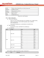
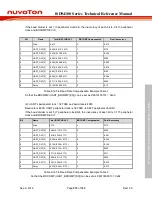
UART0_TXD
Output
UART0 transmit
UART0_RXD
Input
UART0 receive
UART0_nCTS
Input
UART0 modem clear to send
UART0_nRTS
Output
UART0 modem request to send
Table 6.12.4-1 UART Interface Controller Pin
6.12.5 Functional Description
The ISD94100 series UART controller supports four function modes including UART and RS-485.
The current function mode is selected by UART_FUNCSEL register.
6.12.5.1 UART Controller Baud Rate Generator
The ISD94100 series device integrates a programmable baud rate generator.
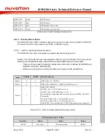
Table 6.12.5-1 describes the baud-rate calculation. Table 6.12.5-2 and Table 6.12.5-3 gives a quick
reference for available baud rates under different mode and BRD setting. In these table:
-
There are three modes for baud rate setting. Baud rate mode is defined by BAUDM0 and
BAUDM1 bits (UART_BAUD[29:28]).
-
BRD value in the formula is defined by BRD bits in register UART_BAUD[15:0].
Mode
BAUDM0
BAUDM1
Baud Rate Equation
Mode 0
0
0
UART0_CLK / [16 * (BRD+2)].
Mode 1
0
1
UART0_CLK / [(1) * (BRD+2)], EDIVM1 must >= 8.
Mode 2
1
1
UART0_CLK / (BRD+2)
If UART0_CLK <= 3*HCLK, BRD must >= 9.
If UART0_CLK > 3*HCLK, BRD must >= 3*N – 1.
N is the smallest integer larger than or equal to the ratio of UART0_CLK /HCLK.
For example,
if 3*HCLK < UART0_CLK =< 4*HCLK, BRD must >=11.
if 4*HCLK < UART0_CLK =< 5*HCLK, BRD must >=14.
(If the UART0_CLK is selected from LXT, BRD can be greater than or equal to 1)
Table 6.12.5-1 UART controller Baud Rate Equation Table
UART Peripheral Clock = 12 MHz
Baud Rate
Mode 0
Mode 1
Mode 2
921600
Not support
Not recommended
BRD=11

