CODEC Motherboard Manual Version 1.3
Page 1 of 66
April 12, 2016
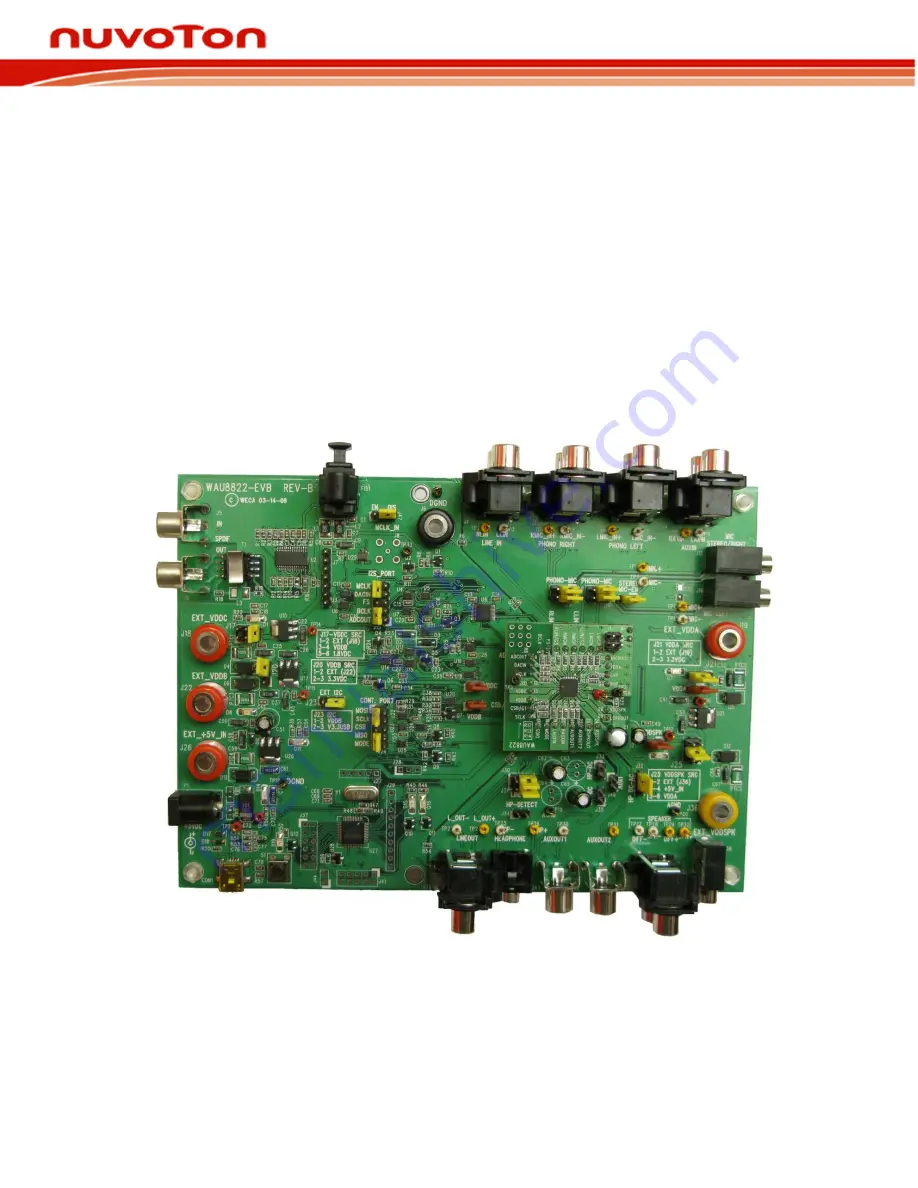
CODEC Motherboard
Nuvoton Audio Codec
Motherboard
Evaluation Board User’s Guide
(For Nuvoton CODEC series: 8812, 8814, 8810, 88C10, 8811, 8820,
8822, 8822L, 88C22, 8401, 8402, 8501, and 8502.)


