Nuvo Renovia Installation Manual Download Page 34

26

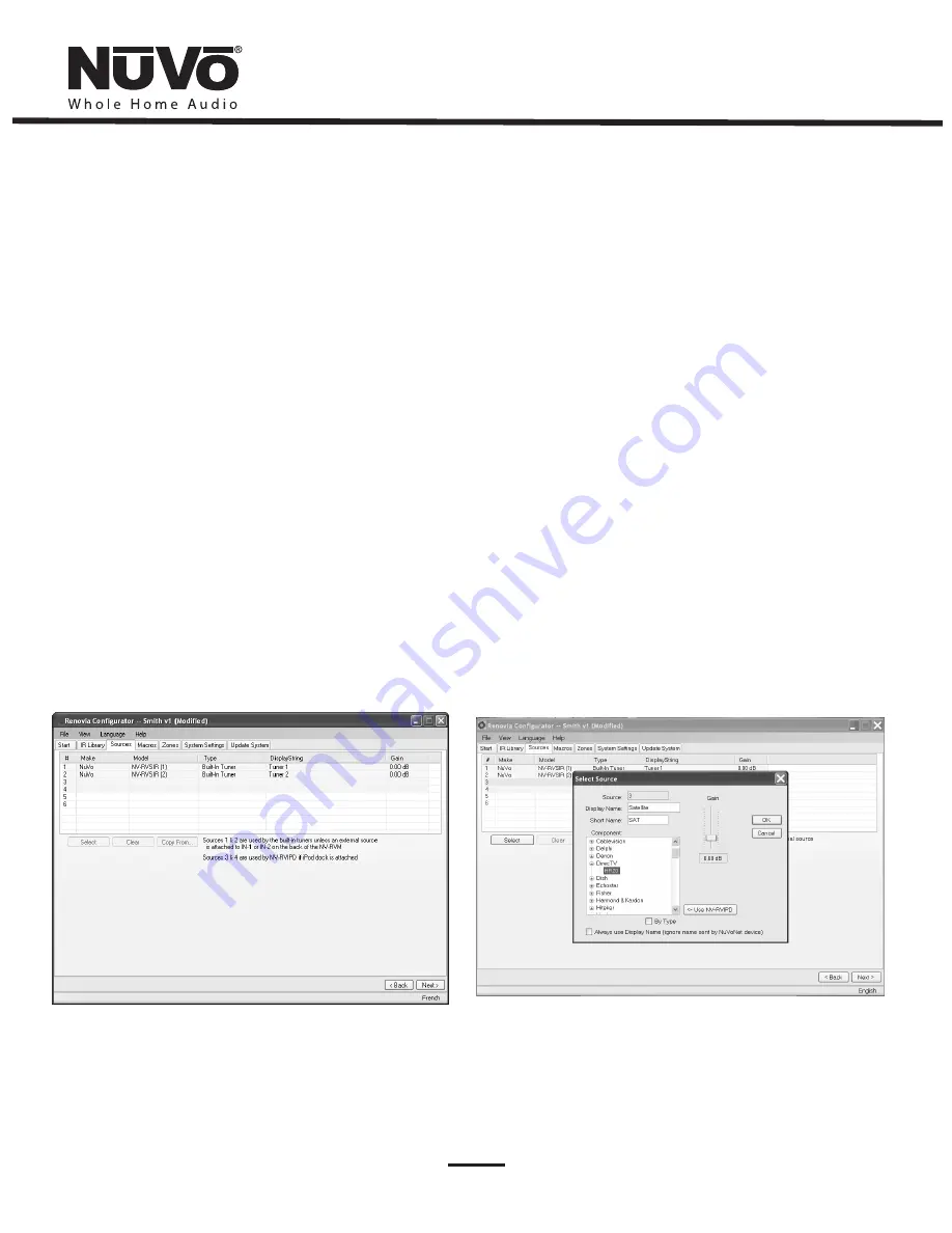
6.3.  Sources Tab (as shown in Fig. 32)

The “Sources” tab allows you to define the source component 
attached to each of the six source inputs. All six sources are not 
needed. If none are defined in the configuration, the configuration 
will initialize and the Hub firmware will default to two activated 
sources, the internal AM/FM/SIRIUS–Ready Tuners on on the Source 
1 and 2 inputs. It should be noted that the Hub will not activate any 
of the sources 3 - 6 for selection that do not have audio cables 
connected, even if they are defined in the configuration that is 
loaded. 

All that is necessary for tuner reception is to attach the included NV-
T2FAA active antenna to the Antenna input on the Main Source Hub.  
These however, can be used for other sources connected to the 
stereo mini 3.5mm jacks on the back panel, if you choose. Highlight 
either of the sources and delete them by clicking on the


Clear


button.  This will allow you to add any other source you choose from 
your IR Library (See Section


6.3.1 Select or Edit Source

).

Source 3 and 4 default to the 9-pin inputs for the NV-RVIPD Renovia 
NuVoDock for iPod.  These however, can be used for other sources if 
you choose.

Fig. 32

Fig. 33

An important feature of the “Select Source” window is the “Gain” 
level control. Different pieces of source equipment tend to have 
different levels of audio output signal. This slider control allows you 
to compensate for equipment that has an inherently lower volume 
level. By using this adjustment, when switching between sources, 
relative volume levels remain constant.

When the appropriate information have been completed, click “OK.” 
This will add the updated source information to the “Source” 
window. When all the desired sources have been defined, go to 
“Next” and proceed to the “Macros” setup.

6.3.1 Select or Edit Source (as shown in Fig. 33)

Double-clicking on a blank source will open the “Select Source” 
window. This window assigns the appropriate source number input. 
The “Display Name” is the text that will be read on the Control Pad 
when that source is selected in any zone. The display name can 
contain only capital letters, numbers, and some punctuation. If an 
invalid key is typed, it will be ignored.  The “Short Name” field is for a 
three character abbreviation that will be used to identify the source 
on the Control Pad display.

Summary of Contents for Renovia

Page 1: ...Renovia System Installation Guide...

Page 2: ......

Page 3: ......

Page 4: ...ION 810 20 GROUNDING CONDUCTORS GROUND CLAMPS POWER SERVICE GROUPING ELECTRODE SYSTEM NEC ART 250 PART H NEC NATIONAL ELECTRICAL CODE ANTENNA LEAD IN WIRE SAFETY NOTE Where the MAINS plug or appliance...

Page 5: ......

Page 6: ...ear water i e bathtub sink swimming pool wet basement etc 6 Only use dry cloth to clean this product 7 Do not block any ventilation openings It should not be placed flat against a wall or placed in a...

Page 7: ...teurs et aux utilisateurs Installation doit tre effectu e conform ment aux dispositions de tous les codes lectriques nationaux et locaux et ne doit tre effectu e par un lectricien correctement sous li...

Page 8: ...eakers and control options a Run speaker wire and Cat5 to double gang wall receptacle located next to a tested electrical outlet b CAT5 is not required if you are using a wireless control pad or a thi...

Page 9: ......

Page 10: ...pply Page 17 3 2 Properly Installing the NV RVZA50 In wall Zone Amplifier Page 17 4 0 Installing the NV RVZAF50S Zone Amplifier 4 1 Properly Installing the Freestanding Renovia Zone Amplifier Page 19...

Page 11: ...uency electrical power and load disturbances a standard residential electrical supply cable can be used in the same way as multi conductor network wiring Thus the daunting task of routing multiple wir...

Page 12: ...ones 4 ControlTX LED This green LED is a diagnostic tool indicating the transmission of control messaging from the NV RVM to any active zones 5 Control RX LED Like the ControlTX LED this yellow LED is...

Page 13: ...IR controlled components Sources plugged into the 1 2 audio inputs will automatically override the internal AM FM tuners A connection to source inputs 3 and 4 will be overridden if a Renovia NuVoDock...

Page 14: ...l as specific zone and system control operations 7 Power This button turns the local zone on and off or turns all zones off simultaneously 8 Play Pause This IR programmable button toggles between the...

Page 15: ...Power This button turns the local zone on and off or turns all zones off simultaneously 7 Menu Menu serves as access to music browsing presets and favorites as well as allowing access to specific zone...

Page 16: ...ndicates that the zone is locked In this state a four digit security code is required to unlock the zone s control features 8 Do Not Disturb This icon indicates that the zone is set for Do Not Disturb...

Page 17: ...local zone on and off or turns all zones off simultaneously 7 CurrentTime and Battery Display This reflects the current time as set up in the NuVo Renovia System Note that it is a Renovia only functio...

Page 18: ...own buttons then press OK to go to the year and use the up down buttons Time use a similar technique to go through and adjust the four time digits and AM PM c Check the rooms list in the Menu Consider...

Page 19: ...tems are running filter them vi Check the Renovia FAQ webpage at nuvotechnologies com for an update on other potential interference sources 2 Turn on possible interference sources which are hard wired...

Page 20: ...utlet that shows a Good rating is an excellent choice for the installation of a Renovia Zone Amplifier If at all possible avoid Poor outlets and minimize the use of those that test Marginal Fig 3 Site...

Page 21: ...orget to use the Menu to re select the previous room name you used and the same outlet number Compare the new reading on the display to the previous reading in the printed log If you see no degradatio...

Page 22: ...es The connections do not become active on the sytem Control Pads until a source is physically plugged in This allows the System to automatically reflect the available sources for the user Although th...

Page 23: ...through Sources 1 and 2 Fig 7 The NuVo active antenna can be located up to 200 feet from the Main Source Hub Your SIRIUSTuners must be activated through SIRIUS This can be done online at www SIRIUS co...

Page 24: ...l Pads the source must have a NuVoNet CAT5 connection from its NuVoNet output to one of the three NuVoNet inputs on the back of the Renovia Main Source Hub An audio connection using the included stere...

Page 25: ...Use wire nuts to connect the black hot white neutral and ground wire leads from the Renovia Power Supply to the corresponding leads from the electrical wire as shown in Fig 12 Install the Power Suppl...

Page 26: ...ly If you are using an in wall single or dual gang Control Pad or the ColorTouch Pad plug the associated CAT5 wire into the NuVoNet CAT5 connection on the back of the Zone Amplifier and plug the termi...

Page 27: ...tlets that are easily accessible if you are intending to use In wall or in ceiling speakers or if you are installing one of the in wall Control Pad options for the zone 4 1 Properly Installing the Fre...

Page 28: ...additional amplification 5 0 Setting the Zone HomePlug Channel If the HomePlug Channel on the Main Source Hub has been changed to one other than A see section 6 6 Using the Configurator Software Syste...

Page 29: ...TREAM CONTROL ZONE RST PWR 1 2 D 3 4 C 5 B 6 A 7 8 AUDIO STREAM CONTROL ZONE RST PWR ZONE 1 2 D 3 4 C 5 B 6 A 7 8 ZONE 1 2 D 3 4 C 5 B 6 A 7 8 NV RVZA50 NV RVZA50 NV RVZAF50S NV RVZAF50S 100 240V 50 6...

Page 30: ...ns The first is used to open an existing configuration or to create a new one The second asks to Retrieve Existing Configuration From Renovia When you click on the Retrieve button a progress window wi...

Page 31: ...utton This will open the IR Library Record window The window will indicate that the Configurator is Waiting for IR Communications To record a new code simply point the component s remote control at th...

Page 32: ...ment that is activated when the button is held The Control Pad automatically displays the function being sent to the source component Once this sequence is completed proceed to the next function comma...

Page 33: ...ox will open where you can record yes or no to the test Three successful test results are required before the Passed count turns green Clicking the OK button will save the results in the IR Library Th...

Page 34: ...9 pin inputs for the NV RVIPD Renovia NuVoDock for iPod These however can be used for other sources if you choose Fig 32 Fig 33 An important feature of the Select Source window is the Gain level contr...

Page 35: ...ity to store specific IR commands as preset names The best example is cable or satellite Using the Macro tab you can establish a preset name and set the appropriate IR commands to select a specific st...

Page 36: ...on the next space and repeat the Macro Definition steps 6 4 2 Editing Codes in a Macro as shown in Fig 37 In the Edit Macro Definition window double clicking on a macro step on the right side will ope...

Page 37: ...e Reset at Zone ON box is checked Max Volume This allows the volume in a zone to be limited This can be done either to avoid damage to low power speakers or simply to prevent a certain room from being...

Page 38: ...system wide commands from a specific zone No Mute The Renovia System has a small accessory called the MI1 Mute Interrupt see section 9 2 NV MI1 Mute Interrupt Adaptor which is designed to mute all zon...

Page 39: ...he definition properties can be modified Wireless Control Pad A zone assignment is required for each Wireless Control Pad up to five being used in the system It is best to use one of the shaded zones...

Page 40: ...he power button turns all the zones off 6 6 5 Security Code A feature with the zone setup of the Renovia System is the ability to lock the zone This can be done as a default that will require a four d...

Page 41: ...e Center since the last configuration load Configurations can always be retrieved and edited at a future date Print Zone Source Summary as shown in Fig 42 A useful function is to click on File and sel...

Page 42: ...lete When the Control Pad is finished upgrading itself it will turn off At that point it is ready for zone control use MENU OK Firmware Upgrade Please Wait Fig 44 Updating device 1 0f 2 If you have ch...

Page 43: ...battery in the Wireless Control Pad This will bring up an initial screen asking if you would like toEnable or Disable the devices Zone button If you choose Enable you are allowing the Zone control of...

Page 44: ...AM or FM the display will also indicate signal strength for the selected frequency as shown in Fig 50 Changing Bands Touching the Play Pause button on the Control Pad will also toggle through the avai...

Page 45: ...e that is chosen Within the Options menu is Edit Favorites as shown in Fig 54 When Edit Favorites is chosen Add to Favorites will allow you to add any playlists or presets as shown in Fig 55 When the...

Page 46: ...highlighted preset from the list Add to Favorites laces the highlighted preset into the Favorites menu available at each Control Pad Move Up and Move Down moves the highlighted preset up or down withi...

Page 47: ...tions this feature is rarely used b Regional Setup Regional Setup sets the default tuning standard for four regions of the world The choices are US Canada Western Europe Australia and New Zealand Cust...

Page 48: ...ftware through the RS232 port AM FM Signal Strength This displays two levels for Tuners A and B RSSI received signal strength indicator is a measurement in dBuV and SNR signal to noise is measured in...

Page 49: ...a specified amount of time as shown in Fig 68 Once the time election is made the system will gradually ramp down in volume and the zone will turn itself off at the end of the selected time Lock Zone...

Page 50: ...Empty Empty Empty Fig 71 Balance This controls the level of audio going to the left and right speakers In some cases when the listening area is not absolutely centered between the speakers it is usef...

Page 51: ...ource Group is that each zone area maintains individual on off and volume capability Default DND This prevents the global functions of all on or party and whole house page from acting on the specific...

Page 52: ...stalled speakers on a zone allowing detection of mechanical mounting problems that can create buzzes and rattles 4 Ohm Speakers This refers to the output of the Zone Amplifier When this is selected th...

Page 53: ...been loaded When selected the first menu displayed will be a selection list all of the existing Zone Names The default is Zone N where N is the zone number Scroll to the one you wish to edit and pres...

Page 54: ...voltage to trigger paging selecting Paging Mode sets the mute input to react and mute all zones If it triggers by creating a closure dropping down to 0 voltage you need to select Active Low Closed Ser...

Page 55: ...in the Learning Station Package This will supply the necessary AC power for IR learning and testing 2 CONNECTTO PC Using one of the supplied RS232 cables connect from the RS232 port on your computer...

Page 56: ...puter at the RS232 port Connect the male end of the RS232 cable to the back of the Interface box into the CONNECTTO PC input At this point it is not necessary to have the Interface box connected to th...

Page 57: ...from the terminals on the doorbell chime to the Doorbell A or Doorbell B inputs on the back of the MI1 Polarity is not important for this connection Up to two phone lines can be brought into the RJ11...

Page 58: ...MUTE The RC1 remote provides a discrete mute function to quickly silence the zone s output 9 SOURCE OK This is another dual function button In normal playback mode it scrolls through the sources and...

Page 59: ...Output DriveVoltage 20 mA 2 5V minimum Compatible with single and dual emitters Input 1 AM FM with RDS Radio Data Service SIRIUS Ready Analog Audio Input 2 AM FM with RDS SIRIUS Ready Analog Audio In...

Page 60: ...o Signal 14VA 7W Power Supply Output 25VDC at 1 4A cont 2 6A peak Efficiency 84 With no ControlPad device connected Average is measured at 1 8 max power 3 125W channel NuVoNet Local NuVoNet Control Pa...

Page 61: ...unication try using the NV HPNF HomePlug filter The zone Control Pad displays Zone Address and does not actually connect with the Main Source Hub The Zone Amplifier and Main Source Hub are set at two...

Page 62: ...Source Hub When downloading a Configuration to the Renovia Main Source Hub a board not found error message appears on the computer screen The computer output communication speed is not compatible wit...

Page 63: ......

Page 64: ...www nuvotechnologies com NuVoTechnologies LLC Hebron Kentucky USA NVRV 1044...

Reviews: