Safety Instructions
8)
Ventilation - The unit should be situated so that its
location or position does not interfere with its proper
ventilation. For example, the unit should not be
situated on a bed, sofa, rug, or similar surface that
may block the ventilation openings; or placed in a
built-in installation, such as a bookcase or a cabinet
that may impede the flow of air through the
ventilation openings.
9)
Heat - The unit should be situated away from heat
sources such as radiators, stoves, or other
appliances that produce heat.
10)
Power sources - The unit should be connected to a
power supply only of the type described in the
operating instructions or as marked on the unit.
11)
Power cord protection - Power-supply cords should
be routed so that they are not likely to be walked on
or pinched by items placed upon or against them,
paying particular attention to cords at plugs,
convenience receptacles, and the point where they
exit from the unit.
12)
Nonuse periods - The power cord of the unit should
be unplugged from the outlet when left unused for
long periods of time.
13)
Object and liquid entry - Care should be taken so
that objects do not fall into or liquids spilled into
the inside of the unit.
14)
Servicing - The user should not attempt to service
the unit beyond those means described in the
operating instructions. All other servicing should be
referred to qualified service personnel.
15)
Damage requiring service - The unit should be
serviced by a qualified service personnel when:
A.
The power supply cord or the plug has been
damaged; or
B.
Objects have fallen, or liquid has spilled into the
unit; or
C.
The unit has been exposed to rain; or
D.
The unit does not appear to operate normally or
exhibits a marked change in performance; or
E.
The unit has been dropped, or the cabinet has
been damaged .
16)
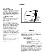
Power lines - An outdoor antenna should be located
away from power lines.
17)
Grounding or polarization - Precautions should be
taken so that the grounding or polarization is not
defeated.
1)
Read instructions- All the safety and operating
instructions should be read before the unit is operated.
2)
Retain instructions - The safety and operating
instructions should be retained for future reference.
3)
Heed warnings - All warnings on the unit and in the
operating instructions should be heeded.
4)
Follow instructions - All operating and other
instructions should be followed.
5)
Water and moisture - The unit should not be used
near water - for example, near a bathtub, washbowl,
kitchen sink, laundry tub, in a wet basement, or near a
swimming pool, etc.
6)
Wall or ceiling mounting - Unit should be mounted to a
wall or
only as recommended by the
manufacturer.
ceiling
7)
Cleaning - The unit should be cleaned only as
recommended by the manufacturer.
Caution
Risk of Electric Shock
Do Not Open
CAUTION: TO REDUCE THE RISK OF ELECTRIC
SHOCK, DO NOT REMOVE COVER (OR BACK). NO
USER - SERVICEABLE PARTS INSIDE. REFER
SERVICING TO QUALIFIED SERVICE PERSONNEL.
WARNING
TO REDUCE RISK OF FIRE OR ELECTRIC SHOCK,
DO NOT EXPOSE THIS UNIT TO RAIN OR
MOISTURE.
The lightning flash with arrowhead symbol
within equilateral triangle is intended to
alert the user to the presence of
uninsulated “Dangerous Voltage” within
the product enclosure that may be of
sufficient magnitude to constitute a risk of
electric shock to persons.
The exclamation point within an
equilateral triangle is intended to alert the
user to the presence of important
operating and maintenance (servicing)
instructions in the literature
accompanying the appliance.


