background image


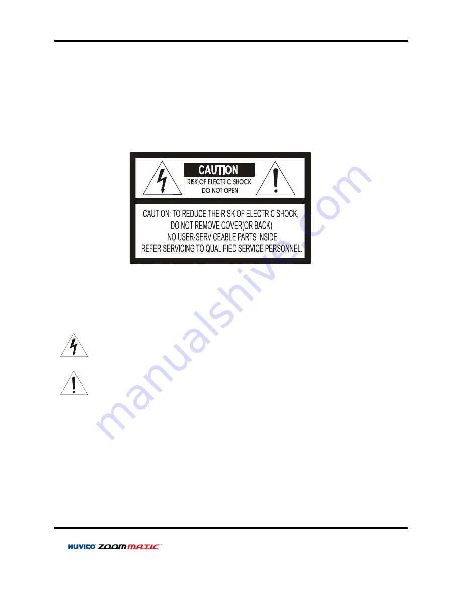
WARNING AND CAUTION 


TO REDUCE THE RISK OF FIRE OR ELECTRIC SHOCK, DO NOT EXPOSE THIS PRODUCT TO RAIN 
OR MOISTURE.  DO NOT INSERT ANY METALLIC OBJECTS THROUGH THE VENTILATION GRILLS OR 
OTHER OPENINGS ON THE EQUIPMENT.

EXPLANATION OF GRAPHICAL SYMBOLS

The lightning flash with arrowhead symbol, within an equilateral   triangle, is intended to 
alert the user to the presence of uninsulated "dangerous voltage" within the product's 
enclosure that may be of sufficient magnitude to constitute a risk of electric shock to 
persons.

The exclamation point within an equilateral triangle is intended to alert the user to the 
presence of important operating and maintenance (servicing) instruction in the literature

WARNING

CAUTION

accompanying the product.


FCC COMPLIANCE STATEMENT 


Summary of Contents for Zoom Matic

Page 1: ......

Page 2: ...2...

Page 3: ...CKET ADJUSTMENTS 11 WIRING DIAGRAM GENERAL OVERVIEW 12 WIRING DIAGRAM CONNECTING TO THE CONTROLLER NVCK 3X 14 WIRING DIAGRAM CONNECTING TO THE DVR 14 REMOTE CONTROLLER SUPPLIED 15 REMOTE CONTROLLER IN...

Page 4: ...rdware CI Z10 30 L 1 Integrated Camera 2 Sunshield 3 Remote Control 4 Instruction Manual 5 Mounting Hardware If any of these materials are missing please contact the vendor or NUVICO customer service...

Page 5: ...ware and software described herein at any time without prior notice No part of this guide may be reproduced transmitted transcribed stored in a retrieval system or translated into any language in any...

Page 6: ...symbol within an equilateral triangle is intended to alert the user to the presence of uninsulated dangerous voltage within the product s enclosure that may be of sufficient magnitude to constitute a...

Page 7: ...ONS OPERATION OF THIS EQUIPMENT IN A RESIDENTIAL AREA IS LIKELY TO CAUSE HARMFUL INTERFERENCE IN WHICH CASE THE USER WILL BE REQUIRED TO CORRECT THE INTERFERENCE AT HIS OWN EXPENSE CAUTION CHANGES OR...

Page 8: ...rotect the power cord from being walked on or pinched particularly at plugs convenience receptacles and the point where they exit from the equipment Only use attachments accessories specified by the m...

Page 9: ...7 Lux Color w Normal Mode 0 03 Lux B W 0 00 Lux IR LED On OSD for Camera Setup 8 Presets Home Function RS 485 Communication IR Remote Controller Supplied 3 Axis Camera View Adjustments Weatherproof IP...

Page 10: ...CV Z10 3 AXIS GIMBAL ADJUSTMENTS 10...

Page 11: ...CI Z10 CI Z30 3 AXIS BRACKET ADJUSTMENTS 11...

Page 12: ...WIRING DIAGRAM GENERAL OVERVIEW 12...

Page 13: ...cting the cables The camera is supplied with second video output on the camera housing To use this feature along with a service monitor second monitor cable is required Using a RS 485 communication it...

Page 14: ...WIRING DIAGRAM CONNECTING TO THE CONTROLLER NVCK 3X WIRING DIAGRAM CONNECTING TO THE DVR 14...

Page 15: ...Change camera ID 4 SAVE Saves preset position 5 PRESET Recall preset 6 HOME Recall Home function 7 MENU OSD menu on 8 DOWN UP LEFT RIGHT Moves up down in the menu Moves left right in the menu Decreas...

Page 16: ...ample To control CAM ID 2 Press 2 and CAM button in sequence 4 WRITE PRESET Saves preset position Example To save Preset 1 Press 1 and WRITE in sequence 5 PRESET Recall preset Example To recall Preset...

Page 17: ...nges in the OSD Setup Menu VIA CONTROLLER NVCK 3X Use the controller to adjust the zoom by twisting the joystick You can also enter and make changes in the OSD Setup Menu VIA DVR Use the DVR s PTZ men...

Page 18: ...d down of the directional buttons on the remote control DVR or from the joystick moves the indicator to the desired feature 4 Move the arrow indicator to the desired feature item 5 Change the status o...

Page 19: ...djusted ZOOM TRK The focus is adjusted with the zoom while in operation ZOOM SPEED Configure zoom speed using this feature FAST To move zoom fast SLOW To move zoom slowly D ZOOM Configure magnificatio...

Page 20: ...de can be used within the color temperature range 3000K 10500 K AWC Auto White Balance Control The white balance is automatically adjusted in a specific environment MANUAL To fine tune select the Manu...

Page 21: ...creen Select END once desired level is obtained IRIS Set IRIS to AUTO or MANUAL Position the indicator over IRIS and then select the desired iris mode AUTO The iris of the lens is automatically adjust...

Page 22: ...to the desired mode HIGH Wide range gain value adjustment NORMAL Normal range gain value adjustment OFF Disabled DNR Digital Noise Reduction Reduces video noise under low Lux environment Position the...

Page 23: ...de HIGH MIDDLE LOW OFF DAY NIGHT Select from COLOR BW or AUTO modes COLOR Color mode B W B W mode AUTO L M H The camera automatically detects lighting conditions and selects the mode accordingly You c...

Page 24: ...nverse the screen SHARPNESS Increasing this value sharpens object edges Too high of a setting however produces noise and may obscure the image COMMUNICATION Use this feature to select communication pr...

Page 25: ...ode But if it is set to OFF it is REMOTE CONTROL for limited operating mode ll Use this feature to change password PASSWORD CHECK The PASSWORD CHECK feature is set to ON pressing MENU to enter the mai...

Page 26: ...o 15 characters CAMERA ID Use this feature to designate an ID for the camera which will display on the monitor screen FUNCTION NAME Use this feature to designate a preset for the camera which will dis...

Page 27: ...e controller or the controller has been idle for programmed time FUNCTION Use this feature to designate preset number for the home WAITING TIME Use this feature to set the dwell time before it goes in...

Page 28: ...nate IRIS mode for preset r preset ut larm output BACKLIGHT Use this feature to designate backlight mode fo TITLE Use this feature to designate preset name for preset ALARM Magnetic PIR or other exter...

Page 29: ...ture to designate preset number for MOTION HOLD TIME Use this feature to designate dwell time of the motion and or r PRIVACY MASK Mask privacy area using this feature The mask area expand contract upo...

Page 30: ...the outer IR and LINE 2 is the inner IR On the CI Z30 there are LINE 1 LINE 4 0 means that IR is turned off and 9 is the at IR s brightest mode Increase or decrease IR level while verifying the change...

Page 31: ...31 NOTES...

Page 32: ...NUVICO Tel 7 495 234 3212 Fax 7 495 234 3212 E mail techsupport nuvico ru www nuvico ru...

Reviews: