


3. Battery Controller
3.1. Overview
Nuvation BMS™ Low-Voltage Battery Controller module safely manages up to 12 or 16 cells by
measuring cell voltage, temperature and current and applying software decision-making to control
contactors, communicate with energy storage controllers, and interface with general purpose I/O.
Battery Controller is able to operate as a stand-alone battery management system, requiring no
additional Nuvation BMS modules to manage a stack of up to 12 or 16 cells.
Battery Controller is available in two models:
• The NUV300-BC-12 which can monitor up to 12 series-connected cells
• The NUV300-BC-16 which can monitor up to 16 series-connected cells
3.2. GPIO Block
The GPIO and control inputs are accessible at the
J5: Control / GPIO connector
.
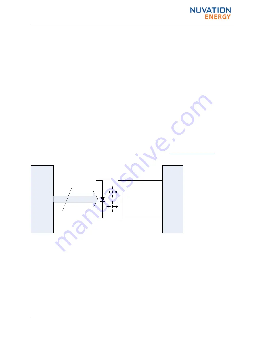
The general-purpose outputs from the Battery Controller are implemented using optical MOSFET
switches. These outputs are non-polarized, presenting an on-resistance of typically 2
Ω
and
capable of carrying 400mA of DC or RMS current when activated.
GPIO Circuit Diagram
shows a
high level circuit diagram for the GPO pins.
GPO_ISOx_B
60V DC Isolation
GPO_ISOx_A
Logic
GPO
x4
GPIO
Figure 2. GPIO Circuit Diagram
The general-purpose and specific-purpose (
FAULT_CLEAR
,
FACTORY_RESET
,
SHUTDOWN
) inputs to the Battery
Controller are implemented using optical isolation components. The current source for these
inputs is provided in the Battery Controller and each input is activated by providing a simple
contact closure to the common point.
The
BMS Enable
input differs slightly from the other specific-purpose inputs. This control requires
a contact closure between the
BMS_ENABLE#
and
VBOT
signals and must not be referenced to the
common point of the other inputs. It is used to start the Battery Controller after it has been shut
down due to activation of the
SHUTDOWN
input, low battery, or some other condition invoked under
software control.
BMS_ENABLE#
is pulled up to the battery stack positive (potentially 60V away from
VBOT
) so the switch/external controller must be tolerant of the maximum battery stack voltage.
Installation Guide - 2018-10-08, Rev. 2.0
4


